Low Cost CNC Machine Shop Houston

Upwards Of 40% of Texas aerospace and energy components now are produced with help from CNC milling. The move toward digital machining has made Houston a key player in high-accuracy manufacturing. Local manufacturers and design engineers often look for Houston-area providers to reduce lead times and maintain quality on high-value assemblies.


The following overview breaks down CNC milling in Houston and its manufacturing advantages. It explains how Houston machining services hold tight tolerances for a wide range of sectors, from oil and gas to biomedical products. If you require a machine shop Houston partner for a first article or large-scale production, Houston supports multiple capable suppliers. Area manufacturers offer 3-, 4-, and 5-axis mills, live-tool turning centers, and EDM support.

The Lowrance Machine operation is an experienced supplier of close-tolerance machining in the area. Contact the team through www.lowrancemachine.com to discuss your engineering requirements, material choices, and scheduling with an experienced provider experienced in precision production and larger production runs.

Key Takeaways

  • CNC Milling Houston is important for local aerospace, energy, and medical manufacturing networks.
  • Houston machining services include high-capability three-, four-, and five-axis milling plus EDM support and turn/mill operations.
  • Selecting a local CNC machine shop Houston can reduce delays and make engineering feedback easier.
  • The Lowrance Machine team manages work from first article through production with documented quality processes.
  • Compare shops on equipment, materials expertise, and room to grow from prototype to volume.

Why Houston Is A Hub For Precision CNC Milling And Industrial Machining

The mix of industries in Houston ensure a constant need for close-tolerance machined parts. Businesses across energy, petrochemical, aerospace, and medical markets require parts with precise fits and inspection records. That requirement supports local machine shops to deliver first articles, assemblies, and repeat-run components.

Over 6,000 manufacturers in the Houston area form a robust supplier network. Machine shops can work alongside local specialty vendors for finishing, thermal processing, and quality checks. The local ecosystem reduces delivery delays, allowing quick engineering revisions for high-detail components.

The Houston region is a key hub for oilfield equipment manufacturing, with direct access to major pipeline routes and port logistics. The city’s transportation advantages make easier the transport of large industrial components to customers worldwide. This efficiency helps both small initial runs and larger production requirements.

NASA’s Johnson Space Center and a thriving aerospace cluster of over 150 companies increase the need for flight-ready parts and test equipment. CNC Milling specialists in Houston find consistent work in machining fixtures, aircraft brackets, and medical components. That type of work demand precise surface finishes and thorough traceability paperwork.

The area’s manufacturing support system supports larger machining programs in Houston. Being close to raw-material suppliers, tooling companies, and metrology labs cuts transit delays. This local advantage is critical for oil, gas, and life-science industries, where part qualification is swift.

Manual Machining Services Houston

CNC Milling Houston

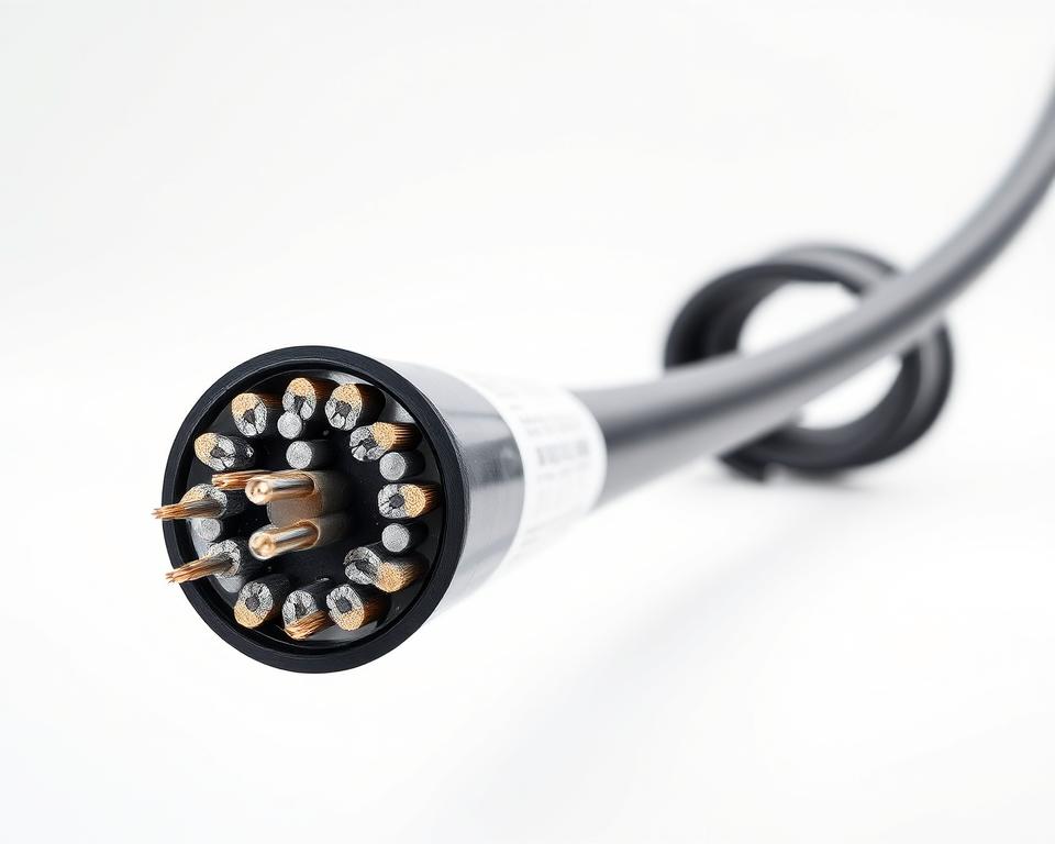
CNC milling converts digital designs into precise metal and polymer parts. The method depends on CNC-driven multi-axis mills. Houston shops apply advanced toolpaths and fast spindle systems to achieve tight tolerances and smooth finishes. Those capabilities support aerospace, medical, energy, and subsea components that need accuracy and small-feature control.

More capable CNC shops combine five-axis equipment with rotary support. This setup allows for difficult profiles to be machined in one setup. It reduces changeovers and reduces delivery schedules for prototypes and production runs. Live-tool lathes plus fast milling allow shops to machine detailed features and small radii accurately.

Definition And Capabilities Of CNC Milling

CNC machining by milling uses programmed motion to remove material with accurate end mills and cutting tools. Simultaneous axis movement supports combined tool movement on three to five axes. This supports the creation of deep pockets, angled faces, and undercut features in one operation. CAM strategies like high-efficiency roughing and adaptive clearing enhance material removal and tool longevity.

Quality-focused Houston machine shops hold tolerances suited to aerospace, medical, and regulated-industry expectations. Precision production uses thermal compensation, rigid spindles, and machine probing for on-machine checks. This equipment ensure parts meet repeatable dimensions and stable geometry across production lots.

Common Equipment And Capacity In Houston Machine Shops

Houston CNC machine shop facilities use machines from established brands such as Mazak, Haas, and DMG MORI. Machines such as DMG MORI NVX and NLVX mills handle 4-axis work with rotary tables for mid-size and larger components. Larger machining-center investments support growth from first article to repeat manufacturing.

Large-format machining centers handle oversized industrial components for pressure-rated housings and offshore hardware. Shops emphasize machines that hold accuracy on large parts, using robust platens and gantry designs. That capability limits outside handling of oversized components and maintains local inspection control.

Shop Capability Typical Hardware Practical Advantage
3-, 4-, 5-axis milling DMG MORI and Mazak multi-axis platforms Complex parts with reduced setup time
Large-envelope machining Gantry mills, Bridge-type centers Precision work on large components
Live-tool turning and milling Turn/mill centers, live-tool lathes Fewer handoffs through combined turning and milling
Fast spindle systems High-RPM spindle units Cleaner finishes and quicker machining
On-machine probing On-machine measurement and Renishaw probes Immediate verification of critical features

Additional support services in a full-service CNC machine shop Houston include precision CNC turning in Houston for round features and follow-up machining. Combining milling and turning limits workpiece movement and reduces total manufacturing time.

Selecting a nearby machining partner with multi-axis capability and trusted brands makes demanding tolerances easier to manage and move projects forward faster. Skilled setup, tooling strategies, and modern equipment create the core of competitive CNC milling Houston services.

Lowrance Machine Services For Precision Manufacturing

Lowrance Machine supports delivering from prototype to production, with attention to precision, timely delivery, and documented quality. It offers a mix of computer-controlled and hands-on machining, supporting short runs, complex parts, and regulated industries. Its team blends modern automation with hands-on skill to meet tight tolerances and schedule demands.

Complete CNC Milling And Machining Services

As a reliable Houston CNC machine shop, Lowrance Machine supports machined components and more complex assemblies. Its capabilities include multi-axis milling, live tooling turning, and long-bed turning for larger or elongated workpieces. EDM services, including wire and probe EDM allow fine detail and internal features that are hard to reach with cutting tools.

Deep-hole gun drilling and BTA drilling handle diameters from 0.25″ up to 3.75″ and long lengths for long-bore applications. Internal value-added services include heat treating, plating, powder coating, and painting so finished parts are closer to installation-ready. That added process support reduce lead time and the need to manage multiple vendors.

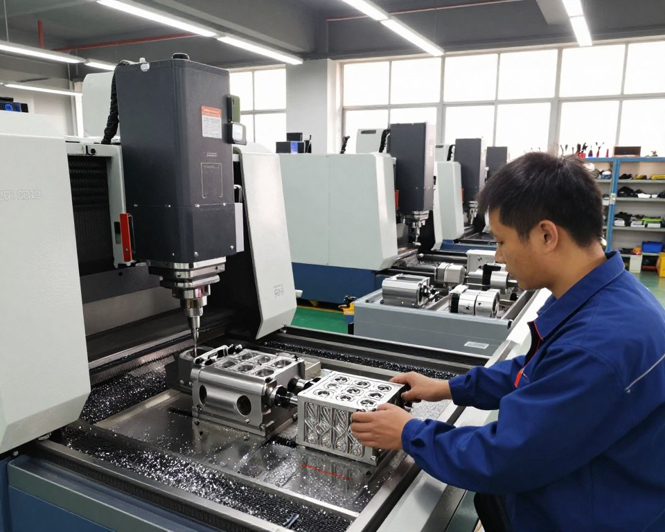
Hands-on machining support in Houston are provided for jigs, fixtures, and low-volume runs. Hands-on specialists handle fits, assembly checks, and one-off modifications that support CNC output. This mix of automated and manual processes helps with quick first articles and a cleaner move into production.

Certifications And Quality Systems

Quality at Lowrance Machine centers on traceable processes and robust inspection. The team uses coordinate measuring, statistical tracking, and EDM-related inspection to ensure repeatable results. These controls serve buyers in regulated and industrial supply chains that require inspection documentation.

Regional machining providers commonly use recognized quality standards such as ISO 9001:2015 and AS9100D to show their quality-management discipline. A regional example is Midway Machine of a Houston-area supplier holding aerospace and general quality certifications, which illustrates common expectations across the market. Lowrance Machine’s process approach aligns to similar industry standards to help satisfy audit and compliance needs.

Support Area Capabilities Customer Advantage
CNC Milling three- to five-axis milling, fast spindles, and hardened-material methods Complex contours, tight tolerances, repeatable runs
Turning & Live Tooling Long-bed turning, multi-turret lathes, live tooling for milling on turning centers Less handling and stronger production efficiency
Wire EDM And Probe EDM Wire EDM, probe EDM verification for internal features Fine detail, burr-free finishes, hardened steel capability
Gun And BTA Drilling Gun/BTA drilling 0.25″–3.75″, extended length options Repeatable long holes and better part performance
Manual Machining Services bench operations, fit-up work, and custom fixtures Flexible support for one-off changes
Metrology & QA coordinate measurement, SPC, probing, and inspection reports Improved traceability and fewer quality escapes
Finishing & Value-Add Heat treat, plating, powder coat, painting, zinc phosphating Simplified logistics with fewer outside vendors

Working with a supplier that pairs broad machining services Houston capabilities with disciplined inspection controls compresses schedules and lowers program risk. Lowrance Machine pairs advanced CNC machine shop Houston capability with skilled machining professionals to support prototypes, production runs, and regulated supply chains.

Materials And Industries Supported By Houston CNC Machine Shops

Machine shops in Houston process a wide range of metallic materials and specialty plastics. They meet strict tolerances and harsh environments. By combining manual skills with automated processes, they produce parts for both heavy industries and precision fields.

Here’s a detailed look at common materials and the industries that rely on them.

Range Of Materials Machined

Alloy steels and carbon steels are key for energy projects, becoming valve bodies, pressure housings, and structural parts. Corrosion-resistant stainless steel is chosen for its resistance to corrosion and easy cleaning.

Copper, bronze, brass, and aluminum are chosen for components needing strength-to-weight ratios and electrical or thermal conductivity. Nickel-based materials withstand subsea, refinery, and high-temperature settings in subsea and refinery settings.

Specialty plastics such as PEEK, Delrin, and UHMW are selected for parts needing wear control, reduced friction, and chemical resistance. They are valuable for assemblies requiring lighter parts or chemical compatibility. Manual machining in Houston supports careful hand finishing on soft or specialized materials, ensuring the final fit and feel.

Industries Served And Example Applications

Oilfield operators and suppliers need subsea hardware, valve bodies, and pressure housings. These parts calls for large-capacity cutting, alignment control, and documented inspection.

Defense and aerospace customers order qualified hardware and testing equipment with strict expectations. CNC Milling in Houston helps achieve tight geometric tolerances on complex aerospace parts.

Medical device and biomedical manufacturers need biocompatible metals and plastics. Regulated medical buyers often expect clean handling plus documented inspection. A dependable Houston machine shop provides batch traceability and stronger documentation for regulatory compliance.

Marine, agriculture, and general industrial production also use Houston machining services. These sectors often require corrosion-resistant fittings, pump components, and custom tooling. The regional market’s broad material capability reflects regional demand, spanning steel grades, aluminum, copper-family alloys, nickel alloys, and specialty plastics. Such materials serve aerospace, biomedical, subsea, energy, marine, and agricultural sectors.

Capabilities And Equipment That Improve Lead Time And Quality

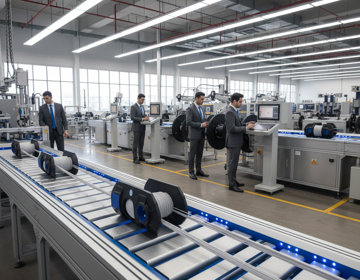
Current-generation Houston machine shops are improving delivery performance and machining consistency with advanced machine tools and efficient workflows. High-speed multi-axis mills, heavy horizontal centers, and long-bed lathes eliminate capacity bottlenecks. The equipment mix, combined with on-site finishing plus metrology, supports quicker and more repeatable outcomes for buyers in multiple industries.

Modern Milling And Turning Machines

High-speed multi-axis mills with indexed rotary support enable engineers to create compound contours in one setup. This reduces cycle time and limits setup-related mistakes. Such capabilities are required by Houston CNC milling providers serving industries with tight tolerances.

Large horizontal machining centers, like the Okuma MB-8000H, machine oversized workpieces. This class of equipment support up to 4,400 pounds and offer large work tables. That allows a single run can consolidate work that might otherwise be split. Long-bed turning Houston capacity is provided by lathes like the Okuma LB line, supporting long cylindrical components up to very long between-center lengths.

Live-tool turning equipment supports milling operations on turning centers. This reduces part handling, lowers cycle time, and reduces re-indicating errors. Providers focused on CNC turning in Houston use live tooling to machine complex turned/milled parts with less handling.

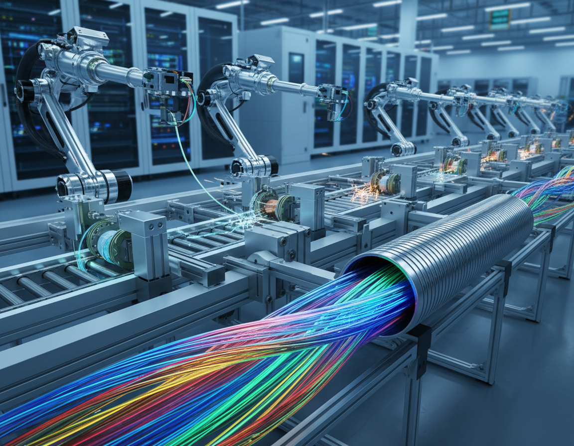
Production Efficiency And In-House Finishing Options

Shop throughput increases when CNC milling machinery in Houston is combined with well-planned fixtures and tool-change automation. Automation such as pallets and gantry loaders help machines stay in cycle while teams set up upcoming work. The outcome is higher throughput and predictable lead times.

Internal finishing services cuts outside queue delays. Frequently used services include thermal processing, coatings, powder coat, paint, and zinc phosphating. A one-stop model for machining services Houston allows customers to receive installation-ready assemblies without managing several outside suppliers.

Production Capability Representative Equipment Main Benefit
High-speed 5-axis milling Haas UMC, DMG Mori DMU Complex shapes in one setup with better finish
Heavy horizontal machining Okuma MB-8000H Fewer setups for heavy components
Long-part CNC turning Okuma LB series, Doosan Puma Efficient production of shafts and housings up to hundreds of inches
Live tooling lathes Okuma live-tool turning platforms Combined turning/milling reduces setups and handling
On-site finishing services Heat treat ovens, plating lines, powder coat booths Reduced outsourcing and more predictable finish quality

Choosing suppliers with this range of equipment compresses schedules and improves repeatability. For work that demands tight tolerances plus fast turnaround, partnering with shops that offer Houston CNC lathe machining, CNC Milling Houston, Houston machining services, and long-bed turning can create significant gains in schedule and product quality.

Choosing The Right Machining Service In Houston: What To Look For

When choosing a provider, match technical capacity to the needs of the part. Ensure the machine envelope, weight capacity, and available axes can handle your components. That is especially important for large or heavy items, where machines like long-bed lathes or large gantry mills are necessary. Confirm the vendor’s ability to handle multiaxis milling for difficult forms and live tooling for fewer-setup operations.

After that, evaluate the vendor’s experience with specific processes. Ask about wire EDM, probe EDM, gun drilling, BTA drilling, and Houston manual machining services for custom, difficult, or repair-focused assignments. A shop with this process mix shows versatility in both first-article and repeat-production settings.

Examine the quality-management systems and measurement tools in place. Ask about AS9100D or ISO 9001:2015 certification and coordinate measuring machines, comparators, and traceable measurement tools. A regional example such as Midway Machine’s AS9100D / ISO 9001 certification exemplifies the area’s aerospace-level quality expectations.

Pay attention to the vendor’s communication speed and estimating accuracy. Quick, detailed quotes that outline tooling, setup times, and inspection steps indicate a capable estimating process and engineering support. A provider that can begin with prototypes and grow into production suggests a more enduring partnership.

Value full-service support to streamline lead times and costs. On-site heat treatment, plating, and finishing reduce subcontract risks and reduce handoffs. That model helps with managing timelines for CNC Milling Houston and other milling tasks.

Use a brief evaluation list to compare candidates’ capacity and equipment. Check largest part envelope, spindle power, and axis options and whether they operate a full CNC machine shop Houston setup plus manual machining services Houston for varied requirements.

Lastly, prioritize clear communication and traceability. Frequent updates, inspection documentation, and one clear contact reduce confusion on demanding programs. Working with a machine shop Houston supplier should function like bringing in an engineering partner and not just a vendor.

Cost, Lead Time, And Scalability For Machine Shop Houston Projects

Understanding price and schedule is critical for technical and procurement teams. These factors are shaped by material selection, machining complexity, and surface expectations. Well-defined requirements are necessary for clear supplier estimates.

What Affects Price And Timing

Choice of material can greatly influence both cost and machining time. For example, aluminum is often faster to machine than stainless steel, which can make stainless jobs slower and harder on tooling. Deep pockets, compound features, and difficult geometry also lengthen machining time. Secondary processes like cryogenic deburring, anodizing, or coatings increase schedule time and raise process-management cost.

Quantity strongly changes unit cost. A first article carries setup and programming costs. By comparison, batch runs spread these costs across multiple parts. Larger production work can justify custom workholding and optimized tooling, shortening each production cycle. Accurate CAD/CAM files with clear tolerances help suppliers quote correctly and reduce delay in supplier responses.

Moving From Prototype To Production

Moving machining from prototype to volume needs stable machines and repeatable processes. Houston shops such as Lowrance Machine invest in high-capacity mills and multi-axis machines. That equipment base helps maintain quality as quantity grows, lowering risk in moving from prototypes into production.

Practical savings methods include turn/mill operations, optimized CAM paths, and dedicated fixturing. That approach cut handling and lower per-part cycle time. Specifying materials and coatings that avoid extra finishing cuts overall cost. CNC Milling Houston capabilities, when planned well, can remove some follow-up work by machining more features at once.

Price estimates and delivery promises are strengthened by clear technical data. Give the shop complete models and drawings, specific inspection requirements, and openness to practical process improvements. Good communication with a shop reduces back-and-forth, creating more predictable delivery and cost outcomes.

Cost Driver Impact On Cost Lead-Time Impact Practical Mitigation
Material choice, such as aluminum vs stainless Aluminum often costs less; stainless can cost more because of tool wear Stainless increases cycle time Choose alloy with similar properties that machines easier
Component complexity and features More complex raises programming and run cost More setups lengthen lead time Apply multi-axis CNC Milling Houston to reduce setups
Tolerances and finish Close tolerances raise inspection and possible rework expense Demanding finishes and tolerances add QA time Balance tolerance to function; limit fine finishes where possible
Volume Larger runs reduce unit cost by spreading tooling expense Production lots add planning time but improve per-part throughput Group quantities to take advantage of tooling amortization
Follow-up finishing processes Coatings, thermal processing, and plating raise total cost Each operation adds transit and queue days Choose materials and finishes that minimize extra steps
CAM and fixture optimization Optimized CAM and workholding lower unit cost Refined setups reduce total production time Work with machining services Houston specialists to refine setups

Final Thoughts

Houston’s industrial manufacturing base is perfect for CNC milling projects in Houston needing accuracy and quick turnaround. Houston providers invest in advanced equipment from brands like DMG MORI and Okuma. These shops may also support EDM, long-bed turning, live-tool lathes, and finishing services. The combined equipment base makes possible smoother progress from first article to repeat manufacturing.

When picking a CNC machine shop Houston, check part specs, volumes, and inspection plans. Verify certifications like ISO 9001 or AS9100D. Transparent pricing and delivery expectations are essential for controlling schedule risk. They help ensure the chosen shop can grow with your needs.

For Houston machining services that include secondary finishing plus assembly help, assess end-to-end capabilities and communication. Lowrance Machine can support the full workflow from prototype to production. The team provides quotes and capability reviews to match your tolerance, material, and delivery requirements.

Implementing Lean Principles in Fiber Cable Sheathing Lines

Eye-opening fact: more than 70% of new U.S. broadband builds now rely on fiber networks that demand precise manufacturing to satisfy performance goals. From material selection through final test reports, Shanghai Weiye OFC Equipment controls FTTH manufacturing to verify 100% quality assurance.

Our drop cable designs are built for aerial, underground, and direct-buried installation, using LSZH, PVC, and PE jackets with 1–4 core configurations. Available options include OS1/OS2, OM2–OM4, G.652D, G.657 variants, Pantone-matched sheath colors, and custom logo printing.

Fiber Secondary Coating Line

Fiber Ribbon Line

Fiber Ribbone Line

precision-driven equipment helps maintain consistent line speed and repeatable output. Standard production windows are usually 4–5 days for orders below 100 km and 7–10 days below 500 km, supported by a 1 km MOQ and free replacement warranty for confirmed quality issues.

Read on to see how materials, testing, and support combine to lower lifecycle cost and match the right product to your network system.

Key Takeaways

  • Shanghai Weiye OFC Equipment delivers end-to-end manufacturing and lab testing for U.S. deployments.
  • Different jacket materials and fiber grades help match diverse installation conditions.
  • Controlled lines and machines support consistent quality and stable optical performance.
  • Fast lead times, low MOQ, and brand fiber options support procurement planning.
  • Comprehensive test reports and warranty support product reliability and documentation needs.

Specialized FTTH Manufacturing By Shanghai Weiye OFC Equipment

Where project timelines and performance matter, Shanghai Weiye OFC Equipment delivers tailored drop solutions with full test documentation.

Shanghai Weiye OFC Equipment works as a focused supplier and manufacturer, pairing specialized equipment with strict material control. We offer customized service and products for residential and MDU rollouts. Every order includes 100% quality assurance and complete test reports.

Our lab conducts high-temperature, salt spray, and vibration tests to verify durability. Available jacket choices include LSZH, PVC, and PE. Designs cover bow-type flat and self-supporting styles and use brand fibers such as Fujikura and Corning SMF-28e.

  • Recorded line controls and production checks support auditable shipments.
  • Engineering assistance covers specifications, sample trials, and volume ramp-up.
  • Modern fixtures and calibration reduce variability so every cable meets operator standards.

Fiber Secondary Coating Line

FTTH Drop Cable Production

At Shanghai Weiye OFC Equipment, manufacturing steps are matched to network specifications, combining brand fiber choices with strict test routines.

Selecting Optical Fiber And Brand Options

Optical fiber is matched according to bend radius, attenuation, and deployment type. Available options include OS1, OS2, OM2–OM4, ITU-T G.652D, and G.657.A1/A2. Brand fiber choices, including Fujikura and Corning SMF-28e, are available to satisfy procurement requirements.

Strength Member Installation

Strength member options include dielectric FRP and metallic steel wire. FRP is ideal where non-conductive runs are required. Steel wire adds tensile strength for longer aerial spans and grounding needs.

Jacket Extrusion And Process Control

Jacket materials include LSZH for indoor flame safety, PVC for flexible handling, and PE for outdoor UV and moisture protection. Careful control of temperature and capstan ratios helps stabilize line speed and maintain dimensional tolerances.

Component FRP Steel strength wire
Best use Dielectric cable routes Aerial spans, high tensile
Advantage Lightweight, inert Greater pulling strength
Installer note Easier terminations Needs proper grounding practice

Inline Testing And Final Inspection

Inline geometry and concentricity checks take place during manufacturing. Final optical testing confirms attenuation and return loss. Each order ships with a 100% test report and lab results from high-temperature, salt-spray, and vibration trials to confirm handling for drop terminations and field use.

Typical lead times are under 100 km in 4–5 days and under 500 km in 7–10 days. Material lot tracking and first-article approvals help support traceability and compliance for U.S. projects.

FTTH Drop Cable Designs And Structures We Manufacture

Shanghai Weiye OFC Equipment builds a focused range of drop cable designs for both tight indoor routing and exposed aerial spans. Every option combines tested materials with geometry designed for field termination and stable optical performance.

Bow-Type Flat For Indoor Distribution

The bow-type flat drop cable minimizes footprint for risers and conduit. The design helps maintain low bend loss for easier routing through hallways and MDUs.

Self-Supporting Designs For Aerial Spans

Self-supporting FTTH drop designs use a messenger element to handle tensile loading. Choose dielectric FRP for non-conductive runs or steel wire when bonding and extra tensile strength are required.

Core Layouts And Strength Member Options

Dielectric and metallic strength member configurations are available to meet safety and EMI requirements. Center loose tube and unitube flat types balance crush resistance and fiber access for quick termination.

Indoor And Outdoor Jacket Options

Jacket choices include LSZH for flame-retardant, low-smoke indoor use and PE for outdoor UV and moisture resilience. Each family is validated for mechanical and optical quality before shipment.

Cable design Best use Strength member Jacket
Flat bow-type Indoor distribution and MDUs Dielectric FRP Low-smoke LSZH
Self-supporting Outdoor aerial routes Metallic steel or dielectric FRP UV-resistant PE
Center-tube design Higher-count routes FRP LSZH or PE
Flat unitube Simple stripping applications Dielectric or metallic strength LSZH/PE

Production Line Equipment For Quality And Speed

At Shanghai Weiye OFC Equipment, automation and sensor-based feedback minimize manual handling while supporting patch cord preparation throughput.

The production line uses automated cutting and stripping machines for drop patch cords, helping increase throughput and reduce labor variation.

The CLX-BPO2 auto-stripping machine operates under PLC and photoelectric control. With a cycle time of about 1.5 seconds, it supports real-world speeds near 20 terminal operations per minute.

Automated Cutting And Stripping For Drop Cable Patch Cords

The equipment strips LSZH and PVC jackets and trims FRP or steel strength members to precise stub lengths. Cylinder-driven actuators deliver fast, repeatable motion and low downtime.

PLC And Photoelectric Control For Precision And Repeatability

PLC logic combined with photoelectric sensors provides accurate positioning and closed-loop control. Inline checks support control charts, helping operators correct process trends before defects increase.

Machine feature Capability Result
CLX-BPO2 unit Fast cycle and automated stripping Around 20 terminals per minute
Actuation Cylinder-based High speed and reliability
Cable handling Jackets and strength members handled together Accurate stubs, clean terminations
Quality control PLC + photoelectric + inline checks Stable quality with fewer corrections
  • Automatic waste ejection and ergonomic loading help keep the work area clean.
  • Control plans record calibration intervals and key operating parameters.
  • Combined machines, fixtures, and trained staff help meet ftth volume goals without sacrificing accuracy.

CLX-BPO2 Auto-Stripping Machine Functions In Our Line

The CLX-BPO2 brings industrial-grade stripping and trimming to our line, cutting cycle time while keeping prep consistent.

Shanghai Weiye OFC Equipment uses the CLX-BPO2 to raise output and standardize terminal quality. The unit runs at an approximate cycle time of 1.5 seconds, yielding about 20 terminal preparations per minute in production.

PLC and photoelectric control support exact detection and repeatable actuation. That control helps keep strip lengths and reserved strength stubs within tight tolerances.

Cycle Time And Throughput

Normal operating speed is about 1.5 seconds per cycle. That speed translates into steady throughput during continuous production.

Supported Jacket Strip And Reserved Strength Lengths

The CLX-BPO2 strips LSZH and PVC jackets with an adjustable jacket strip length from 17.5 to 35.0 mm. Reserved strength member stubs can be set from 7.0 to 11.0 mm to fit common termination hardware.

Handling FRP And Steel Wire Reinforcement

The machine cuts FRP and steel wire strength elements cleanly while helping protect nearby fibers. Customized cutters are available for nonstandard sizes to preserve precision.

  • Automatic waste ejection and sensor-triggered start reduce idle time.
  • Compact size (L40 × W18 × H18 cm), 110–220V, 50W, and 11 kg weight ease integration into workcells.
  • Cylinder-driven movement and PLC/photoelectric control help improve reliability and reduce maintenance interruptions.
Specification Rated value Operational benefit
Cycle time ~1.5 s (~20/min) High throughput for production runs
Strip lengths (A) 17.5–35.0 mm Supports common connector prep
Reserved stub (B) 7.0 mm to 11.0 mm Fits common terminal hardware
Electrical and size data 110–220V and 50W; 40×18×18 cm Simple integration into existing workcells

By using this machine, Shanghai Weiye OFC Equipment standardizes preparation so field teams receive drop components ready for fast installation. The CLX-BPO2 supports production volume targets while helping maintain quality.

Customized Specifications To Fit Your FTTH System

Shanghai Weiye OFC Equipment configures each build to meet your network requirements and simplify field rollout. Clear options and predictable manufacturing windows help your teams receive products that are ready to install.

Core Counts, Fiber Types, And Cable Colors

Select 1–4 core designs using single-mode or multimode fiber. Options include OS1, OS2, OM2–OM4, G.652D, and G.657 variants to suit your optics and connector plans.

We match sheath colors to Pantone codes for fast field ID and consistent asset tagging.

Jacket Choices, Print Legends, And Logos

Choose LSZH, PVC, or PE jackets according to the installation route and safety requirements. Custom print legends and logos support inventory and warranty tracking.

Cable Lengths, Packaging, And Special Structures

Standard lengths include 1 km, 2 km, and 4 km, with customized reels and packaging for storage and handling needs. Bow-type flat or self-supporting designs can be paired with steel wire or FRP strength members to match span, bonding, and isolation requirements.

Choice Typical choice Benefit
Cable length 1 km, 2 km, or 4 km Reduced staging and simpler reel handling
Jacket LSZH, PE, PVC Better fit for installation conditions
Design type Flat or aerial-ready design Routing and span flexibility

As a supplier, Shanghai Weiye coordinates production with your schedule and provides documentation listing final specifications for easier on-site QA.

Testing, Documentation, And Quality Assurance

Shanghai Weiye OFC Equipment builds quality checkpoints into the production line so each item ships with documented acceptance data.

Laboratory Testing For Heat, Salt Spray, And Vibration

The lab performs high-temperature exposure, salt spray corrosion, and vibration testing to qualify materials and assemblies. These tests simulate field stresses for both indoor and outdoor applications.

Complete Test Reports For Every Cable

Each fiber optic cable ships with a complete test report recording attenuation, return loss, and geometry where relevant. Final inspection gates stop nonconforming items before they leave the factory.

Compliance And Traceability

Batch records tie test data to reels and serials so audits and warranty claims are simple to verify. Documentation can follow common customer templates to speed approval and inbound inspection.

  • Line checks and final inspection prevent field failures and lower warranty events.
  • QA packages include specifications confirmation and formatted test data for rapid review.
  • Ongoing test trends guide preventive maintenance and improve long-term reliability.
Lab test Testing purpose Verified outcome
High-temperature test Heat resistance Validated heat endurance
Corrosion exposure Outdoor corrosion screening Verified outdoor readiness
Vibration Resistance to handling stress Reduced field failures

FTTH Drop Cable Pricing And Cost Drivers

Planning the budget for a drop cable run begins with fiber and jacket choices, then adjusts for volume and customization.

Typical prices range broadly—from about $30 to $1,000 per unit—based on fiber grade (G.652/G.657/OM2–OM4), jacket chemistry (LSZH, PVC, PE), length, and structural design.

Material Choices, Fiber Grade, Jacket Type, And Structure

Main cost drivers include fiber optic grade, jacket material, and the cable structure selected for deployment.

Self-supporting designs and steel strength elements increase material and labor input. Custom colors, logos, and print legends add setup time and influence price for short runs.

Price Impact Of Length, Volume, And Custom Options

Longer reels and higher volume orders lower unit cost. Smaller quantities often involve setup fees and higher per-unit pricing.

  • Machine changeovers and special cutters can increase lead time and cost.
  • Clear RFQs and production scheduling help Shanghai Weiye OFC Equipment match price quotes with delivery windows.
  • Framework agreements and indexed pricing can help stabilize budgets across rollout phases.
Cost factor Price impact Suggested approach
Fiber specification Major impact Match performance to budget
Jacket material Material-dependent impact Choose based on lifecycle cost
Cable quantity and reel length High impact Consolidate runs to cut unit cost

Lead Times, MOQ, And Delivery For The United States

Shanghai Weiye OFC Equipment makes lead times and logistics clear so planners can align crews and sites. Predictable delivery windows help reduce downtime and control costs during active rollouts.

Production Windows And Capacity Planning

Typical production windows are 4–5 days for orders below 100 km and 7–10 days for orders below 500 km. Line capacity is scheduled around rollout milestones to support on-time delivery.

The service team provides production updates and tracking details so installers know when reels will arrive. For tight schedules, we hold contingency capacity to accelerate critical-path orders.

Minimum Order Quantity And Why It Matters

The MOQ is 1 km. This accounts for setup needs, including wire and jacket die adjustments, that use start-up material and create scrap.

Length and staging plans are reviewed to choose reel sizes that reduce waste and handling. Batch releases can balance inventory carrying costs with more frequent, smaller job-site deliveries.

Installation Readiness And Use Scenarios

Site conditions dictate whether a self-supporting span, duct pull, or direct-buried run is the best fit for a project.

Deployment Considerations For Aerial, Duct, And Direct-Buried Routes

For aerial routes, Shanghai Weiye OFC Equipment recommends self-supporting designs with suitable strength members to manage sag, tension, and long-term reliability.

Duct installations work best with low-friction jackets and crush-resistant structures that help protect fibers during pulling. PE jackets are common for underground and buried paths where moisture resistance matters.

Direct-buried designs require proper depth control per local codes and moisture-resistant jackets to protect the optic core over time.

Indoor Riser And Plenum Distribution With ONT Termination

Indoor riser and plenum routes favor LSZH jackets to meet flame and smoke rules. Flat drop cable forms strip cleanly and present controlled strength stubs for quick ONT termination.

We guide the choice of steel or FRP (dielectric) strength members based on bonding needs, lightning exposure, and hardware compatibility. Standardized production-line preparation helps shorten installation time and reduce scrap.

Application Important feature Installation tip
Pole route Self-supporting, steel or FRP Check tension and messenger hardware
Conduit route Low-friction jacket, crush resistance Use correct pull tape and lubricant
Direct-buried Moisture-resistant PE jacket Comply with local burial codes
Inside route LSZH sheath with bend control Protect bend radius through penetrations

Our approach ensures a consistent install experience across indoor outdoor transitions. That leads to fewer callbacks, faster activations, and reliable field performance for your system.

End-To-End Support And After-Sales Assistance

Our team coordinates tests, line schedules, and installation guidance to remove surprises during deployment.

Shanghai Weiye OFC Equipment supports engineering from initial requirements through approved drawings and pre-production builds. We deliver documentation templates and clear installation notes so field crews work from the same plan.

After-sales service covers rapid response, root-cause analysis, and corrective actions. All products ship with full test reports and traceability to help QA acceptance.

  • 24/7 availability for status updates and technical guidance.
  • Warranty support includes free replacement when confirmed quality problems occur.
  • Coordination of line schedules for urgent changes or acceleration requests.
  • Configuration control helps ensure shipped items match agreed requirements each time.
Support category Support provided Benefit
Spec engineering Drawing review and trial production Cleaner rollout planning
Testing Laboratory trials and complete test reports Documented product quality
After-sales service Fast replacement and root-cause review Reduced downtime

Summary

Choose Shanghai Weiye OFC Equipment for tailored drop builds, short lead times, and traceable quality records.

We provide customized FTTH drop solutions that combine material selection with validated manufacturing and laboratory testing. Each reel ships with complete test reporting and documented trials to support U.S. field acceptance.

A strong production line, including CLX-BPO2-enabled preparation machines, reduces variation and improves turnaround. Our equipment and machines standardize strip and stub lengths so installers see consistent results at turn-up.

From fiber selection through jacket, printing, and packaging, we balance design and cost to support longer service life. Dedicated support helps manage scheduling, logistics, and after-sales service so deployment remains on track.

Contact Shanghai Weiye OFC Equipment to align specs, timeline, and volume. We stand behind every fiber optic and optic cable shipment with lab validation and responsive service.

SZ Stranding Line Safety and Operator Training Essentials

Above 65% of recent broadband deployments in metropolitan U.S. projects now require fiber-to-the-home. This accelerated move toward full-fiber networks highlights the immediate need for high-performance production equipment.

Fiber Secondary Coating Line
Fiber Coloring Machine
Compact Fiber Unit

Shanghai Weiye Optic Fiber Communication Equipment Co (www.weiye-ofc.com) delivers automated FTTH cable manufacturing line systems for the U.S. market market. Their turnkey FTTH Cable Production Line for High-Speed Fiber Optics combines machines together with control systems. It manufactures drop cables, indoor/outdoor cables, together with high-density units for telecom, data centers, and LANs.

This advanced FTTH cable making machinery delivers measurable business value. It offers higher throughput and consistent optical performance with low attenuation. It also complies with IEC 60794 and ITU-T G.652D / G.657 standards. Customers see reduced labor costs and material waste through automation. Full delivery services cover installation and operator training.

The FTTH cable line output line package contains fiber draw tower integration, a fiber secondary coating line, as well as a fiber coloring machine. This system also contains SZ stranding line, fiber ribbone line, compact fiber unit assembly, cable sheathing line, armoring modules, as well as testing stations. Control as well as power specs commonly use Siemens PLC with HMI, operating at 380 V AC ±10% together with modular power consumption up to roughly 55 kW depending on configuration.

Shanghai Weiye’s customer support model offers on-site commissioning by experienced engineers, remote monitoring, and rapid troubleshooting. This system also offers lifetime technical support together with operator training. Clients are typically required to coordinate engineer logistics as part of standard supplier practice when ordering from FTTH cable machine suppliers.

Core Takeaways

  • FTTH cable line solutions meet growing U.S. demand for fiber-to-the-home deployments.
  • Complete turnkey systems from Shanghai Weiye combine automation, standards compliance, and operator training.
  • Modular configurations use Siemens PLC + HMI and operate near 380 V AC with up to ~55 kW power profiles.
  • Built-in modules cover drawing, coating, coloring, stranding, ribbon, sheathing, armoring, and testing.
  • Modern FTTH cable manufacturing systems reduces labor, waste, and improves optical consistency.
  • Service coverage includes on-site commissioning, remote diagnostics, and lifetime technical assistance.

SZ stranding lines

Understanding FTTH Cable Production Line Technology

This fiber optic cable line output process for FTTH requires precise control at every stage. Cable makers use integrated lines that combine drawing, coating, stranding, together with sheathing. That method boosts yield together with speeds up market entry. This line serves the needs of both residential together with enterprise deployments in the United States.

Here, we summarize the core components and technologies driving modern manufacturing. Each module must operate with precise timing and reliable feedback. The choice of equipment shapes product quality, cost, and flexibility for various cable designs.

Core Components In Modern Fiber Optic Cable Manufacturing

Secondary coating lines apply dual-layer coatings, often 250 µm, using high-speed UV curing. Tight buffering and extrusion systems deliver 600–900 µm jackets for indoor and drop cables.

SZ stranding lines use servo-controlled pay-off and take-up units to handle up to 24 fibers using accurate lay length. Fiber coloring machines use multi-channel UV curing to mark fibers to industry color codes.

Sheathing and extrusion stations produce PE, PVC, or LSZH jackets. Armoring units add steel tape or wire for outdoor protection. Cooling troughs and UV dryers stabilize profiles before testing.

How Production Systems Evolved From Traditional To Advanced

Early plants used manual and semi-automatic modules. Lines were separate, with hand transfers and basic controls. Modern facilities shift toward PLC-controlled, synchronized systems with touchscreen HMIs.

Remote diagnostics as well as modular turnkey setups allow rapid changeover between simplex, duplex, ribbon, together with armored formats. That transition supports automated fiber optic cable production together with reduces labor dependence.

Key Technologies Driving Industry Innovation

High-precision tension control, based on servo pay-off as well as take-up, keeps geometry stable during high-speed runs. Multi-zone temperature control using Omron PID together with precision heaters supports consistent extrusion consistency.

High-speed UV curing and water cooling improve profile stabilization while reducing energy rely on. Integrated inline testers measure attenuation, geometry, tensile strength, crush resistance, as well as aging data.

Operation Typical Module Benefit
Fiber drawing Draw tower with closed-loop tension feedback Uniform core size and low attenuation
Coating stage Dual-layer UV curing coaters Even 250 µm coating that improves durability
Identification coloring Multi-channel fiber coloring machine Accurate identification for splicing and installation
Stranding SZ stranding line, servo-controlled (up to 24 fibers) Stable lay length for ribbon and loose tube designs
Sheathing & extrusion Energy-saving extruders with multi-zone heaters Precise jacket dimensions in PE, PVC, or LSZH
Protection armoring Steel tape/wire armoring units Improved outdoor mechanical protection
Profile cooling & curing Cooling troughs plus UV dryers Quicker profile setting with fewer defects
Testing Real-time attenuation and geometry measurement Live quality control and compliance reporting

Compliance with IEC 60794 and ITU-T G.652D/G.657 variants is standard. Manufacturers typically certify to ISO 9001, CE, and RoHS. These credentials help support diverse applications, from FTTH drop cable production to armored outdoor runs and data center high-density solutions.

Choosing cutting-edge fiber optic production equipment and modern manufacturing equipment enables firms meet tight tolerances. Such equipment selection enables efficient automated fiber optic cable production and positions companies to deliver on scale and quality.

Essential Equipment In Fiber Secondary Coating Line Operations

This secondary coating stage is critical, giving drawn optical fiber its final diameter and mechanical strength. The line prepares the fiber for stranding as well as cabling. A well-tuned fiber secondary coating line controls coating thickness, adhesion, as well as surface consistency. It protects the glass during handling.

Producers aiming for high-yield, fast-cycle fiber optic cable manufacturing must match material, tension, and curing systems to process requirements.

High-speed secondary coating processes rely on synchronized pay-off, coating heads, and UV ovens. Modern systems achieve high production rates while minimizing excess loss. Precise tension control at pay-off and winder stages prevents microbends and ensures consistent coating thickness across long runs.

Single and dual layer coating applications address different market needs. Single-layer setups provide basic mechanical protection and a simple optical fiber cable production machine footprint. Dual-layer lines combine a harder inner layer with a softer outer layer to improve microbend resistance and stripability. That helps when fibers are prepared for connectorization.

Temperature control as well as curing systems are critical to final fiber performance. Multi-zone heaters together with Omron PID controllers guide screw/barrel extruders to stable melt flow for LSZH or PVC compounds. UV curing ovens as well as water trough cooling stabilize the coating profile and reduce variation in excess loss; targets for high-output quality single-mode fiber often aim for ≤0.2 dB/km at 1550 nm after extrusion.

Key components from trusted suppliers improve uptime as well as precision in an optical fiber cable line output machine. Extruders such as 50×25 models, screws together with barrels from Jinhu, and bearings from NSK are common. Motors from Dongguan Motor, inverters by Shenzhen Inovance, as well as PLC/HMI platforms from Siemens or Omron deliver robust control as well as monitoring for continuous runs.

Operational parameters shape preventive maintenance and process tuning. Typical pay-off tension ranges from 0.4 to 1.5 N for fiber reels, while radiation and curing speeds are adjusted to material type and coating thickness. A preventive maintenance cycle around six months keeps secondary coating processes stable and supports reliable high-speed fiber optic cable production.

Fiber Draw Tower And Optical Preform Handling

The fiber draw tower is the core of optical fiber drawing. It softens a glass preform in a multi-zone furnace. Then, it pulls a continuous strand with precise diameter control. This step sets the refractive-index profile and attenuation targets for downstream processes.

Process control on the tower uses real-time diameter feedback as well as tension management. That prevents microbends. Cooling zones together with closed-loop systems keep geometry stable during the optical fiber cable manufacturing process. Current towers log metrics for traceability as well as rapid troubleshooting.

Output quality supports single-mode fibers such as ITU-T G.652D and bend-insensitive types like G.657A1/A2 for FTTH networks. Draws routinely meet stringent loss figures. Excess loss after coating is kept at or below 0.2 dB/km for high-performance single-mode fiber.

Integration with secondary coating lines requires careful pay-off control. A synchronized handoff preserves alignment and tension as the fiber enters coating, coloring, or ribbon count stations. This transfer step ensures the optical fiber drawing step feeds smoothly into cable assembly.

Equipment vendors such as Shanghai Weiye offer turnkey options. These include testing stations for attenuation, tensile strength, and geometric tolerances. These services help manufacturers scale toward fast-cycle fiber optic cable line output while maintaining ISO-level output quality checks.

Key Feature Purpose Typical Goal
Multi-zone heating furnace Uniform preform heating for stable glass viscosity Consistent draw speed and refractive profile
Real-time diameter control Maintain core/cladding geometry and reduce attenuation ±0.5 μm tolerance
Managed tension and cooling Reduce microbends and maintain fiber strength Target tension based on fiber type
Automated pay-off integration Smooth transfer to coating and coloring Synchronized feed rates for zero-slip transfer
Integrated online testing stations Verify loss, strength, and geometry Loss ≤0.2 dB/km after coating for single-mode

Advanced SZ Stranding Line Technology In Cable Assembly

This SZ stranding method creates alternating-direction lays that cut axial stiffness and boost flexibility. As a result, it is ideal for drop cables, building drop assemblies, as well as any application that needs a flexible core. Manufacturers moving toward automated fiber optic cable manufacturing employ SZ approaches to meet tight bend together with axial tolerance specs.

Precision in the stranding stage protects optical performance. Modern precision stranding equipment uses servo-driven carriers, rotors, and modular pay-off racks that accept up to 24 fibers. These systems deliver precise lay-length control and allow quick reconfiguration for different cable types.

Automated tension control systems keep fibers within safe limits from pay-off to take-up. Servo pay-offs, capstans, and haul-off units maintain constant linear speed as well as target tensions. Typical fiber pay-off tension ranges from 0.4 to 1.5 N while reinforcement pay-offs run between 5 as well as 20 N.

Integration using a downstream fiber cable sheathing line streamlines line output as well as lowers handling. Extrusion of PE, PVC, or LSZH jackets at 60–150 m/min syncs featuring stranding through a Siemens PLC. Cooling troughs as well as UV dryers stabilize the jacket profile right after extrusion to prevent ovality and reduce mechanical stress.

Optional reinforcement and armoring modules add strength without compromising flexibility. Reinforcement pay-off racks accept steel wires or FRP rods. Armoring units wrap steel tape or wire with adjustable tension to meet specific mechanical ratings.

Built-in quality control prevents defects before cables leave the line. In-line geometry checks, fiber strain monitors, and optical attenuation measurement detect excess loss or mechanical strain caused by stranding or sheathing. These checks support continuous automated fiber optic cable manufacturing workflows as well as cut rework.

The combination of a robust sz stranding line, high-end precision stranding equipment, together with a synchronized fiber cable sheathing line provides a scalable solution for manufacturers. This blend raises throughput while protecting optical integrity and mechanical performance in finished cables.

Fiber Coloring Machine And Identification Systems

Coloring and identification are critical in fiber optic cable production. Accurate color application minimizes splicing errors and accelerates field work. Modern equipment combines fast coloring with inline inspection, ensuring high throughput and low defect rates.

Today’s fast-cycle coloring technology supports multiple channels together with quick curing. Machines can operate 8 to 12 color channels simultaneously, aligning using secondary coating lines. UV curing at speeds over 1500 m/min helps ensure color as well as adhesion stability for both ribbon together with counted fibers.

The following sections discuss standards as well as coding prevalent in telecom networks.

Color coding adheres to international telecom standards for 12-color cycles and ribbon schemes. That consistency aids technicians in installation and troubleshooting. Consistent coding significantly cuts field faults and accelerates network deployment.

Quality control integrates high-spec fiber identification systems into manufacturing lines. In-line cameras, spectrometers, as well as sensors detect color discrepancies, poor saturation, and coating flaws. This PLC/HMI interface alerts to issues and can pause the line for correction, safeguarding downstream processes.

Machine specifications are vital for uninterrupted runs and material compatibility. Leading equipment accepts UV-curable pigments and inks, compatible with common coatings and extrusion steps. Pay-off reels accommodating 25 km or 50 km spools ensure continuous operation on high-volume lines.

Supplier support is essential for US manufacturers adopting these technologies. Shanghai Weiye as well as other established vendors offer customizable channels, remote diagnostics, as well as onsite training. That support model reduces ramp-up time together with enhances the reliability of fiber optic cable manufacturing equipment.

Specialized Solutions For Fibers In Metal Tube Production

Metal tube and metal-armored cable assemblies provide robust protection for fiber lines. They are ideal for direct-buried and industrial applications. The controlled routing of coated fibers into metal tubes prevents microbends, ensuring optical performance remains within specifications.

Processes depend on precision filling and centering units. These modules, in conjunction with fiber optic cable manufacturing equipment, ensure concentric placement and controlled tension during insertion.

Armoring steps involve the use of steel tape or wire units with adjustable tension and wrapping geometry. This process benefits armored fiber cable production by preventing compression of fiber elements. It also keeps reinforcement wires at typical diameters of ø0.4–ø1.0 mm.

Coupling armoring with downstream sheathing as well as extrusion lines results in a finished outer jacket made of PE, PVC, or LSZH. An optical fiber cable line output machine must handle pay-off reels sized for reinforcement and align featuring sheathing tolerances.

Quality checks include crush, tensile, and aging tests to confirm the armor does not exceed allowable stress on fibers. Standards-based testing ensures long-term reliability in field conditions.

Turnkey solutions from established manufacturers integrate metal tube handling with SZ stranding and sheathing lines. These solutions include operator training and maintenance schedules to sustain throughput on fiber optic cable manufacturing equipment.

Buyers should consider compatibility with armored fiber cable production modules, ease of changeover, and service support for field upgrades. These factors reduce downtime and protect investment in an optical fiber cable production machine.

Fiber Ribbon And Compact Fiber Unit Manufacturing

Modern data networks require efficient assemblies that pack more fibers into less space. Manufacturers employ a fiber ribbon line to create flat ribbon assemblies for rapid splicing. This method uses parallel processes and precise geometry to meet the needs of MPO trunking and backbone cabling.

Advanced equipment ensures accuracy and speed in production. A fiber ribbon line typically integrates automated alignment, epoxy bonding, precise curing, and shear/stacking modules. In-line attenuation and geometry testing reduce rework, maintaining high yields.

Compact fiber unit production focuses on tight tolerances and material choice. Extrusion and buffering create compact fiber unit constructions with typical tube diameters from 1.2 to 6.0 mm. Common materials include PBT, PP, and LSZH for durability and flame performance.

High-density cable solutions aim to enhance rack together with tray efficiency in data centers. By increasing fiber count per unit area, these designs shrink cable diameter together with simplify routing. They are compatible with MPO trunking together with high-count backbone systems.

Production controls and speeds are critical for throughput. Modern lines can reach up to 800 m/min, depending on configuration. PLC and HMI touch-screen control enable quick parameter changes and synchronization across multiple lines.

Quality and customization remain key differentiators for manufacturers like Shanghai Weiye. Electronic monitoring, customizable ribbon counts, stacking patterns, and turnkey integration with sheathing and testing stations support bespoke high-speed fiber cable production line requirements.

Key Feature Ribbon Line Compact Unit Benefit for Data Centers
Line speed Up to roughly 800 m/min Up to 600–800 m/min More output for large deployment projects
Core processes Automated alignment, epoxy bonding, curing Extrusion, buffering, and tight-tolerance winding Improved geometry consistency with lower insertion loss
Primary materials Engineered tapes and bonding resins PBT, PP, LSZH jackets and buffers Durable performance and safety compliance
Inspection Inline attenuation and geometry checks Tension monitoring and dimensional control Fewer field failures and quicker deployment
System integration Sheathing and splice-ready stacking Modular compact units for dense cable solutions Streamlined MPO trunking and backbone builds

Optimizing High-Speed Internet Cable Production

Efficient high-speed fiber optic cable production relies on precise line setup and strict process control. To meet US market demands, manufacturers must adjust pay-off reels, extrusion dies, as well as tension systems. This helps ensure optimal output for flat, round, simplex, as well as duplex FTTH profiles.

Cabling Systems Used In FTTH Applications

FTTH cabling systems must accommodate various drop cable types while maintaining consistent center heights, like 1000 mm. Production lines for FTTH include 2- and 4-reel pay-off options. They also feature reinforcement pay-off heads for enhanced strength.

Extruder models, such as a 50×25, control jacket speeds between 100 and 150 m/min, depending on LSZH or PVC. Extrusion dies for 2.0×3.0 mm profiles guarantee reliable jackets for field installation.

Quality Assurance In The Fiber Pulling Process

Servo-controlled pay-off as well as take-up units regulate fiber tension between 0.4–1.5 N to prevent excess loss. Inline systems conduct fiber pull testing, attenuation checks, mechanical tensile tests, as well as crush and aging cycles. These tests verify performance.

Key control components include Siemens PLCs and Omron PID controllers. Motors from Dongguan Motor and inverters from Shenzhen Inovance ensure stable operation and easier maintenance.

Meeting Industry Standards For Optical Fiber Drawing

A well-tuned fiber draw tower produces fibers that meet ITU-T G.652D and G.657 standards. The goal is to achieve ≤0.2 dB/km excess loss at 1550 nm for high-quality single-mode fiber.

Choosing the best equipment for FTTH cables involves evaluating speed, customization, warranty, and local after-sales support. Top FTTH cable production line manufacturers deliver turnkey layouts, remote monitoring, as well as operator training. This cuts ramp-up time for US customers.

Closing Summary

Advanced FTTH cable making machinery integrates various components. These include fiber draw towers, secondary coating, coloring lines, SZ stranding, as well as ribbon units. This system additionally includes sheathing, armoring, together with automated testing for consistent high-speed fiber manufacturing. A complete fiber optic cable production line is designed for FTTH together with data center markets. This line enhances throughput, keeps losses low, together with maintains tight tolerances.

For U.S. manufacturers as well as system integrators, partnering featuring reputable suppliers is key. They should offer turnkey systems with Siemens or Omron-based controls. This includes on-site commissioning, remote diagnostics, and lifetime technical support. Companies like Shanghai Weiye Optic Fiber Communication Equipment Co provide integrated solutions. Such solutions simplify automated fiber optic cable manufacturing as well as reduce time to line output.

Technically, ensure line configurations adhere to IEC 60794 and ITU-T G.652D/G.657 standards. Verify tension together with curing settings to meet excess loss targets, such as ≤0.2 dB/km at 1550 nm. Adopt preventive maintenance cycles of roughly six months for reliable 24/7 operation. When planning a new FTTH cable production line, first evaluate required cable types. Collect product drawings and standards, request detailed equipment specs as well as turnkey proposals, together with schedule engineer commissioning together with operator training.

The Future of Precision Machined Parts in the Semiconductor Industry

“Foresight without action is hallucination.” – Thomas Edison. This statement speaks directly to product development. A clever design exists as an idea until it turns into a tangible, testable part.

UYEE Prototype connects this gap. We are a established provider of precision fabrication services. We excel at transforming the adaptable thermoplastic ABS into durable components.

Titanium Precision Parts

ABS Machining

Precision Machined Parts

Acrylonitrile Butadiene Styrene provides an outstanding balance of properties. It provides high impact resistance, solid strength, and dimensional stability. This makes it a fundamental choice for structural applications across many fields.

Our sophisticated computer-controlled cutting process turns solid blocks into accurate, functional items. This approach avoids the need for expensive injection molds. It is a budget-conscious path for low to medium-volume runs and rapid development cycles.

Industries from automotive to consumer electronics rely on these durable plastic parts. They are used for jigs, fixtures, and end-use products. The key is choosing an experienced manufacturer.

UYEE Prototype combines material science with manufacturing expertise. We guide clients through design for manufacturability and achieving tight tolerances. This partnership ensures your vision is executed with quality and efficiency.

Introduction To CNC Machining ABS Prototypes

The journey from digital design to physical part depends on selecting the right combination of material and manufacturing process. For countless engineers, the answer lies in a common thermoplastic and a precise, computer-controlled fabrication method.

This synergy creates durable, functional items suitable for testing and use. Understanding the material’s science and the process’s advantages is the first step.

What Is ABS Material? Understanding Acrylonitrile Butadiene Styrene

ABS stands for acrylonitrile butadiene styrene. It is a popular thermoplastic polymer. Its name reflects its three-monomer copolymer structure.

Acrylonitrile provides chemical resistance and thermal stability. Butadiene provides toughness and impact strength. Styrene brings rigidity and ease of processing.

This blend produces a material known for excellent toughness and good dimensional stability. It maintains its shape under load, which is crucial for structural applications.

Titanium Precision Parts

“The material you choose is the foundation of your product’s performance.”

Engineering Standard

Key property metrics help guide specification. Heat deflection temperature indicates how well a part performs under thermal stress. Rockwell hardness measures resistance to indentation.

Specialized grades, like ABS Flame Retardant, are available for added safety compliance. This variant meets specific industry standards.

Why Choose CNC Machining For ABS Prototypes?

Several methods exist for creating plastic parts. Computer-controlled cutting stands out for functional models. It provides “true material behavior” since the item is milled from a solid block.

This preserves the full mechanical properties of the final production plastic. Other techniques, like vacuum casting, may use secondary materials that don’t match.

Process flexibility is a major advantage. Design iterations can happen rapidly without expensive tooling investment. It is perfect for low-volume runs and complex geometries.

The cost-effectiveness for small quantities is significant. High-quality surface finishes and precise details are achieved directly from the machine.

For functional testing, design validation, and presentation-quality models, this approach offers an optimal blend. It delivers fidelity, speed, and economic value.

At UYEE Prototype, our expertise in material science guides this selection. We ensure your components meet both performance and budgetary goals.

Key Advantages Of CNC Fabricated ABS Prototypes

Selecting the right method for creating plastic components hinges on three fundamental pillars: economy, material performance, and precision. These advantages directly lead to reduced project risk and a smoother path from concept to validated product.

Cost-Effectiveness And Rapid Lead Times

The economic case for this fabrication method is strong. It eliminates the high upfront cost of injection molds.

This makes it ideal for quantities from a single piece to over a hundred. The entry price point for initial models is very low.

Speed is equally critical. At UYEE Prototype, project lead times can start at just 3 days.

This rapid turnaround enables fast design iteration. It significantly shortens your overall time-to-market.

Superior Material Properties: Strength, Toughness, And Dimensional Stability

The chosen thermoplastic delivers remarkable performance. It offers high impact resistance and good tensile strength.

This inherent resilience and rigidity often outperform other commodity plastics at a similar cost. Components can absorb shock without failing.

Dimensional stability is a critical property. It ensures parts maintain their precise shape and fit within assemblies.

This stability holds true across a range of environmental thermal conditions. It is essential for functional testing and end-use deployments.

Key Material Trait Advantage for Engineered Components
Excellent Impact Durability Resists sudden impacts and drops, which is ideal for housings and enclosures.
Solid Tensile Strength & Stiffness Maintains structural integrity under tension and bending forces.
Excellent Dimensional Stability Preserves accurate geometry and fit, crucial for assemblies.

Precision And Tight Tolerances In Fabrication

Geometric accuracy is a cornerstone of our service. Standard machining accuracies are held to ±0.010 inches.

Tighter accuracy targets, such as ±0.002 inches, are readily achievable. For demands below ±0.002 inches, our experts conduct a manual review to ensure feasibility.

Smart engineering design optimizes both overall cost and quality. Avoid specifying excessively tight dimensional requirements unless absolutely necessary.

Grouping features on the same axis planes minimizes machine complexity. Keeping internal corner radii and tapped hole sizes consistent reduces tool changes.

UYEE Prototype offers components in natural beige, white, or black. For surface texture, you may choose the standard “As Machined” look or a uniform matte “Bead Blast” finish.

“Accuracy in prototyping confirms accuracy in production.”

UYEE Prototype Machining Principle

These advantages combine to deliver reliable, high-fidelity parts. They empower your engineering team to reduce risk and confirm performance with confidence.

Uses And Industries For ABS Prototypes

From sleek consumer gadgets to rugged industrial equipment, specific thermoplastics prove their worth through versatile application. The theoretical benefits of precision-fabricated parts become concrete when they meet real-world demands.

This section explores major sectors where these components excel. Each industry leverages unique material properties to solve distinct challenges.

UYEE Prototype has extensive experience across these diverse fields. We help clients translate design intent into functional, reliable items.

Consumer Electronics: Housings And Enclosures

The consumer electronics sector demands a delicate balance. Parts must be lightweight yet durable, aesthetically pleasing, and precisely fitted.

This plastic offers an ideal combination of impact resistance and excellent surface finishability. It protects delicate internal circuitry while providing a sleek, user-friendly exterior.

Common applications include laptop cases, television bezels, and game controller bodies. These housings and enclosures require perfect fit for internal components.

Home appliance bodies also benefit from the material’s good strength and dimensional stability. UYEE’s fabrication ensures tight tolerances for seamless assembly.

This results in presentation-ready models that look and perform like final products. It allows for thorough user testing and design validation before high-volume production.

Automotive Components: Interior Trim And Functional Parts

In the automotive world, components face a harsh environment. They must withstand temperature fluctuations, UV exposure, and physical wear.

Interior trim pieces, like dashboard panels and pillar covers, are prime examples. The material provides a desirable feel, finish, and cost-effectiveness for these visible parts.

Its toughness and rigidity are crucial for functional items under the hood or on the exterior. Applications include grilles, spoilers, and specific bumper components.

“The right material in the right place defines quality and safety in automotive engineering.”

Dimensional stability ensures these parts maintain their shape and fit across a wide temperature range. This property is non-negotiable for both safety and aesthetics in vehicle manufacturing.

From prototype to low-volume production, this approach allows for rapid iteration of complex geometries. It accelerates development cycles for both interior and exterior applications.

Industrial Manufacturing: Jigs, Fixtures, And Machine Housings

Industrial settings prioritize utility, durability, and cost-efficiency. Here, the focus shifts to custom tooling and equipment that streamline production.

Custom jigs, fixtures, and assembly aids are typical applications. These tools guide workers or machines during manufacturing, ensuring consistency and quality.

The material’s strength, machinability, and low cost make it perfect for these utilitarian roles. Protective housings for machinery and control panels are also common.

These enclosures and cable management parts shield sensitive electronics from dust, debris, and incidental impact. Rapid production of such custom components enables faster production line setup and modifications.

UYEE Prototype’s expertise ensures these industrial parts are robust and precisely made. They withstand the rigors of the factory floor, proving the material’s value from the design lab to operational deployment.

The versatility of this solution is clear. It supports innovation from initial concept through functional testing and into low-volume manufacturing.

By understanding sector-specific needs, UYEE delivers parts that perform as intended. This partnership turns ambitious designs into tangible, reliable components.

Why Partner With UYEE Prototype For Your ABS Needs

Your project’s outcome depends on a collaborator who understands both the science of materials and the art of fabrication. UYEE Prototype offers this dual expertise, guiding you to the optimal manufacturing process.

We provide deep knowledge of thermoplastics, including specialized grades for specific applications. Our team excels in precision fabrication, holding tight tolerances and machining complex geometries.

For functional testing and low-volume runs, computer-controlled cutting delivers true material properties in days. When appearance matters for small batches, vacuum casting offers a cost-effective alternative. High-volume production later benefits from injection molding.

We act as your consultative partner, offering design for manufacturability feedback to optimize cost and performance. Our rapid lead times and transparent pricing keep projects on schedule.

Value-added services like surface finishing and assembly deliver ready-to-use components. Submit your CAD files to our team for a professional review and quote. Let’s transform your design into a tangible success.

Ribbon Identification and Marking Post-Ribbon Line Process

Unexpected fact: By October 2023 this initiative touched 151 countries, covering roughly $41 trillion in GDP and about 5.1 billion people — a scale that materially shifted global trade pathways. Here, “facilities connectivity” refers to how Beijing financed and built cross-border systems—ports, rail, and digital links—that bind regions together. This opening section summarizes what was intended between 2013 and 2023, what was built, and where controversies intensified.
BRI Facilities Connectivity
Expect a short trend review: the early megaproject push, then a shift toward greener, smaller, and more digital initiatives. We’ll map the policy toolkit, corridor planning, financing patterns, and who benefited.

This piece weighs the key tension: infrastructure as a development opportunity versus concerns about debt, governance, and geopolitics. Case studies include CPEC/Gwadar, Indonesia’s high-speed rail, and the Port of Piraeus to ground the analysis.

Belt And Road Facilities Connectivity In Context: What The Belt And Road Initiative Set Out To Do

When Xi Jinping introduced the New Silk Road in 2013, he reframed infrastructure as a vehicle for shared growth across continents.

Origins And The New Silk Road Narrative

President Jinping used the silk road label to build legitimacy and win partner buy-in. That name helped unify and rebrand many national plans under a single global program.

Scale And Reach By October 2023

By October 2023, the Belt and Road effort included 151 countries, spanned around $41 trillion in combined GDP, and reached roughly 5.1 billion people. This size made the belt road effort a system-level force, not a regional push.

Why “Connectivity” Became The Umbrella Objective

Connectivity bundled transport, energy, communications, investment flows, and people movement into one policy narrative. The logic was clear: reduce time and cost for trade, broaden market access, and make cross-border movement more predictable.

Metric Amount Role
Countries involved 151 Program reach
Combined GDP $41 trillion Market scale
People covered ~5.1 billion Human scale

The Chinese government framed the initiative as a platform using state finance, SOEs, and diplomacy to deliver projects at scale. Ambition was clear, but formal policy blueprints were needed to turn vision into on-the-ground corridors.

From Vision To Implementation: The Policy Blueprint That Guided BRI Connectivity

The 2015 Action Plan converted a broad policy aim into a clear operating manual for cross-border work. It laid out steps that made planning, finance, and people exchanges practical for many projects.

TTH Cable Production Line

The 2015 Action Plan Targets

The plan named four targets: improve intergovernmental communication, align infrastructure plans, build soft infrastructure, and deepen people-to-people ties.

Intergovernmental Coordination

Stronger coordination meant national plans matched at key stages. That reduced political risk and lowered the chance projects stalled after a leadership change.

Aligning Transport And Power

Alignment efforts focused on linking transportation systems and power grids across borders. The approach aimed to support industrial zones and urban growth with reliable routes and energy.

Soft Infrastructure, Financial Integration

Soft infrastructure included trade deals, harmonized standards, faster customs, and financial integration to smooth cross-border payments and capital flows.

People-To-People Connections

Education exchanges, joint research, and tourism created the human networks needed to operate and sustain long-term projects.

Goal Main Action Expected Outcome
Coordination Intergovernmental forums Reduced policy reversals
Plan alignment Transport/power mapping Connected routes, steady supply
Soft infrastructure measures Trade rules and finance links Smoother cross-border trade
People ties Scholarships & exchanges Local capacity plus trust

How The Silk Road Economic Belt And The 21st Century Maritime Silk Road Shaped Routes

Two route systems—overland corridors across Eurasia and maritime networks at sea—set the spatial logic for major investments. This dual-track approach guided where money, equipment, and construction teams focused work over the past decade.
Belt and Road Financial Integration

Overland Connections Across Eurasia And Central Asia

Overland corridors prioritized rail, highways, and pipelines that cross Central Asia. Those corridors aimed to shorten transit times for exporters and cut reliance on long sea voyages.

Rail connections through Central Asia became crucial as a bridge between producers and markets. Planners often bundled towns, terminals, and logistics parks into corridor plans.

Maritime Logistics: Ports, Sea Lanes, And Hinterland Links

The maritime silk road approach translated into three operational parts: port expansion, use of major sea lanes, and inland links that make ports useful. Ports served as hubs where ships meet rail and road for last-mile movement of goods.

Why Connecting Land And Sea Routes Mattered

Linking routes built strategic redundancy. If chokepoints threatened shipping lanes, overland options could route traffic elsewhere and keep goods moving.

Reliable route options increased predictability for shippers. That helps firms plan inventory, reduce buffer stocks, and stabilize supply chains.

  • Two-route architecture focused capital on nodes that link land and sea.
  • Corridors turned route maps into investment bundles—ports, terminals, rail links, and customs nodes.
  • Real projects required financing, regulation, and operators to work together.

Economic Corridors And Facilities Connectivity: What Corridor Development Meant In Practice

Building an economic corridor meant pairing hard works—roads, rail, ports—with softer measures that make places productive.

Corridor development was a bundle: transport links, logistics nodes, industrial clustering, and policy changes that ease trade. The goal was to turn transit routes into engines of local growth.

Corridors As More Than Infrastructure

Productive integration explains this plainly. Manufacturing, power supply, and distribution networks were aligned so corridors created jobs and exports rather than just transit fees.

Planners added warehouses, customs hubs, and special zones to capture value near the route. That helped move goods faster and supported local firms.

Where Corridor Planning Connected With Local Development

Local strategies, including industrial parks, city-region plans, and land policy, aimed to capture spillovers from corridor projects.

Aspect Area Objective Risk Example
Transport expansion Reduce travel time Underutilization if demand lags CPEC bundles multiple asset types
Industrial clusters Create jobs, exports Weak zoning blocks growth Special zones near terminals
Regulatory changes Speedier customs and licensing Reform delays can cut benefits Local trade rule alignment

Over time, focus shifted from raw construction to utilization, revenue models, and long-run competitiveness. Corridor-scale work is capital-intensive and usually needs state-linked finance and strong political coordination to proceed.

Financing The Connectivity Push: Chinese Banks, Institutions & Competitive Bidding

Cheap, patient capital from Chinese policy banks rewired which projects could start and which stalled. That funding model was central to how many large transport and port projects progressed from 2013 to 2023.

Two policy lenders—China Development Bank (CDB) and the Export-Import Bank of China (EXIM)—received big capital injections. Their bonds trade like government debt and they can access People’s Bank liquidity. That gave them very low borrowing costs and flexible terms.

The result: Chinese SOEs won many bids by offering attractive finance packages. Between 2013 and 2023, about $1 trillion in investment and construction deals were signed with partner countries. That scale made cheap credit a defining feature of the initiative.

Competitive bidding often depended on finance terms as much as technical offers. Recipient governments sometimes preferred faster, less-conditional loans over longer, conditional multilateral options.

Still, financing did not eliminate implementation risk. Indonesia’s high-speed rail offer won on strong Chinese investment and credit, but land acquisition and licensing delays slowed progress.

Beyond contracts, the model supported industrial policy: steady overseas pipelines kept SOEs busy and built execution experience. In turn, finance capacity shaped which sectors dominated early work—transport, energy, and port infrastructure—setting up the next phase of outcomes.

Past Project Patterns: Transportation, Energy & Ports That Anchored Facilities Connectivity

Early patterns clustered around three physical pillars: transport routes, power buildouts, and major seaports. That mix made routes practical for trade and connected inland production to overseas markets.

Flagship Corridor Case: A Long Kashgar–Gwadar Link

The China-Pakistan Economic Corridor runs roughly 3,000 kilometers from Kashgar to Gwadar. This project bundles highways, rail, pipelines, and optical cables to give inland China faster maritime access.

Multi-Asset Packages

Corridor bundles combined transportation nodes with power plants and digital links. Putting roads, rails, fiber, and grid works together shows how infrastructure went beyond single projects.
Belt and Road People-to-People Bond

Energy-First Investment Profiles

Many corridors prioritized energy first. Large power plants and grid upgrades often came before industrial parks so factories had reliable supply.

Ports And Strategic Nodes: Gwadar And Piraeus

Gwadar was leased to a Chinese ports operator until 2059, but rollout lagged—airport and free-zone timelines slipped and usable acreage remained small in 2023. That slowed cargo flows and local benefits.

By contrast, COSCO’s majority stake at Piraeus gave operators direct control and a foothold into European logistics. These two examples show how ownership and execution shaped real gains.

When energy, transport, and port work align, corridors cut costs and speed goods movement; when they don’t, utilization and benefits lag.

Economic And Trade Effects: How Connectivity Initiatives Influenced Growth And Integration

Shorter transit routes and smoother border processes made new markets reachable for many exporters. Reduced shipment time cut logistics costs and improved delivery predictability.

Firms could reduce inventory buffers. That increased the appeal of exporting manufactured goods to farther markets and supported regional trade growth.

How Faster Movement Of Goods Changed Trade

Lower transport costs and steady schedules raised the volume of traded goods on several corridors. Faster delivery made perishable and time-sensitive products viable for export.

Measured effects included shorter lead times, cheaper freight per unit, and higher shipment frequency for certain routes.

Financial Integration: RMB Use And Bond Issuance

Issuing bonds in RMB and promoting local currency use reduced currency friction. That helped buyers and lenders avoid costly currency conversions and built deeper capital links.

RMB-denominated instruments also made Chinese investments easier to price and finance across borders.

Channel Mechanism Likely Impact Example
Transport upgrades Shorter routes plus better terminals Lower freight costs and faster delivery Rail and port packages
RMB bonds Local issuance plus currency swaps Lower exchange risk, deeper markets RMB bond initiatives
SOE capacity export Overcapacity deployed abroad Increased project supply, lower prices Steel and construction exports

Domestic Drivers And Regional Reshaping

Behind the projects were domestic aims: keeping state firms busy, exporting excess steel and cement, and deploying large national savings overseas.

Over time, expanding links can shift regional trade patterns and deepen some countries’ economic reliance on a major partner. That reshaping can lift productivity but also increase political leverage.

Partner countries can gain jobs, better logistics, and growth when projects fit local needs and governance is strong. However, benefits depend on sound project choice, transparency, and complementary reforms.

Scale creates both benefits and risks. The same forces that raise trade and financial integration also amplify concerns about debt, governance, and underperforming projects—issues explored next.

Constraints And Controversies That Shaped Outcomes Over The Past Decade

A mix of financial strain, governance gaps, and execution bottlenecks shaped how many projects performed across partner countries. These limits forced policy shifts and changed public perceptions of large-scale investment programs.

Debt Stress And Cautionary Cases

Sri Lanka and Zambia became cautionary examples. Debt strain and repayment concerns shifted political debate and led some governments to renegotiate or halt deals.

“Repayment stress can shift public opinion and push governments to rethink long-term commitments.”

Governance And Corruption Risks

Weak oversight increased value-for-money concerns. Low 2022 CPI scores—Turkmenistan (19), Pakistan (27), Sri Lanka (36)—help explain recurring concerns about transparency and fraud.

Execution Bottlenecks, Underperformance

Common delays came from land acquisition, licensing, procurement disputes, and cost overruns. Indonesia’s high-speed rail missed early targets for those reasons.

Kenya’s railway stopped short of the Uganda border, and a parliamentary review found rail freight could cost more than road transport. Incomplete networks lower returns and spark political backlash.

Constraint Example Impact Policy Response
Debt sustainability risk Sri Lanka and Zambia Renegotiation, public protests Review of loan terms
Governance risks Low CPI scores Value-for-money doubts Transparency initiatives
Execution bottlenecks Indonesia high-speed rail Cost overruns; slow utilization Stronger procurement rules
Underuse Kenya rail shortfall Lower economic returns Project review

Geopolitics And A Pandemic-Era Slowdown

Geopolitical skepticism from the U.S. and some allies reduced high-level participation and nudged some countries away from large deals. Italy signaled shifting interest, for example.

Investment flows also dropped: outbound construction and investment in 2022 were $68.3B, down from $122.5B in 2018. That ~44% fall showed a clear momentum shift.

Taken together, these constraints forced adaptation and set the stage for a 2023 pivot toward greener, digital, and integrity-focused cooperation.

How BRI Connectivity Began Evolving By 2023: From Megaprojects To Green And Digital Links

By 2023, the initiative’s playbook clearly shifted from headline megaprojects to targeted, lower-risk efforts. The white paper released in October framed the shift as a move toward smaller projects that emphasize sustainability, tech collaboration, and cross-border digital trade.

Signals From The 2023 White Paper And Forum Priorities

The 2023 white paper and the Third Forum emphasized a multidimensional network instead of one-off giants. Xi listed commitments that highlighted green development, science and technology cooperation, and stronger institutions.

New Emphasis: Green Development, Science & Technology, E-Commerce

Green development responds to environmental critiques and tighter financing. Smaller renewable projects and upgrade work can be approved and funded faster, with clearer permits and less social backlash.

Digital and e-commerce links widen the initiative’s scope. Data flows, platforms, and cross-border trade systems now sit alongside ports and rails as core parts of future integration.

Institution-Building And Integrity-Based Cooperation

Greater focus on integrity and institution building aims to manage debt and transparency risks. Stronger procurement rules, compliance checks, and joint oversight reduce political and financial friction for partners and lenders.

AI Governance And Shaping Rules

The Global Initiative for Artificial Intelligence Governance signals a shift toward setting norms, not only building assets. Rule-making in AI and standards work can shape influence in the 21st century as much as physical projects once did.

Implication: This pivot changes how partner countries measure success. Future influence will come from greener projects, digital platforms, and shared rules—tools that are harder to quantify but may prove more durable.

Conclusion

In summary: Years of rapid projects reshaped routes and reduced trade frictions, but outcomes differed by country. Success depended on clear economics, strong governance, and timely delivery.

Over the decade the belt road approach moved from big, hard infrastructure builds to a more selective, reputation-aware agenda. By 2023, the initiative emphasized green development, digital links, and stronger institutions.

Key mechanisms to remember are route architecture (land and sea), corridor development logic, and financing driven by policy lenders and state firms. Major controversies—debt stress, corruption risks, execution delays, and geopolitical pushback—drove the shift.

Watch next: green project pipelines, e-commerce platforms, and AI governance. For U.S. audiences, this evolution matters for standards, supply-chain routing, port influence, and the competitive landscape for development finance.

CNC Precision Machining for Renewable Energy Components

KZD-CncMmachining.com proudly excels in delivering CNC Precision Machining expertise across many market sectors such as aerospace, medical, energy, and automotive. It uniquely combines state-of-the-art machining equipment with a team of veteran engineers. Their purpose is to transform intricate designs into tangible products. Notable facilities including RAM Tool and WessDel shops exemplify excellence with their expansive capabilities, commitment to ISO-certified quality systems, and a wide mix of machines that handle large workpieces and strict precision demands.

Advanced CNC precision machining significantly decreases production cycle times, minimizes waste, and enhances product consistency. This is achieved through a synergy of CAD/CAM-driven programming, advanced machining centers, and rigorous quality controls. A trusted CNC shop offers customizable CNC machining and contract manufacturing services. It readily transitions from initial prototype stages to comprehensive production volumes, prioritizing careful inspection and product traceability at every step.

At KZD-CncMmachining.com, we pride ourselves on a client-focused approach, exhaustive metrological analysis, plus providing complete start-to-finish solutions. Our expertise caters to single-run CNC machining projects and the mass production of high-volume components. With the right blend of advanced machinery plus disciplined process control, we guarantee consistent, precise results.

Key Takeaways

  • KZD-CncMmachining.com focuses on CNC Precision Machining for many industries.
  • Advanced machines such as 5-axis machining and horizontal mills improves capability for complex parts.
  • CNC precision machining reduces errors and increases repeatability using CAD/CAM and inspection.
  • Custom CNC machining plus scalable CNC services cover prototype work through production runs.
  • Quality systems and metrology are essential for meeting tight tolerances and industry standards.

CNC Precision Machining Services

Digital designs are transformed into exact parts for aerospace, medical, and industrial uses via CNC precision machining. Specialists at operations like RAM Tool and Precision Automation facilities use CAD/CAM files to set up equipment. They employ mills, lathes, and CNC routers to produce dies, prototype tooling, and custom components. Detailed inspections and on-time deliveries remain central to this workflow.

CNC Precision Machining

Definition And Core Benefits Of CNC Precision Machining

CNC production moves cutting tools through computer-based numerical control, ensuring unparalleled accuracy. It remarkably diminishes manual preparation, curtails cycle times, and minimizes errors. Services often include milling, turning, true 5-axis machining, and wire EDM, tackling detailed geometries and strict tolerances with efficiency.

Typical Tolerances And Material Capabilities

Precision machining routinely reaches tolerances as minute as 0.0002″ on steel and titanium alloys like Ti-6Al-4V. Commonly machined stainless grades are 15-5, 17-4, 304, 316, and 420. The spectrum of materials spans from aluminum and zinc alloys for die casting to durable steels, titanium, and engineered plastics for a range of industrial needs.

How Precision CNC Machining Reduces Errors And Improves Repeatability

CAM programming, robust tool libraries, and automated probing reduce variation, improving consistency. Measurement tools like CMMs and laser scanners strengthen part-to-part accuracy. This efficiency accelerates the transition from prototypes to full production and ensures tight quality control supported by traceable documentation.

Comprehensive CNC Machining Services For Custom Components

Manufacturers often need broad capabilities to quickly produce precision parts. Modern CNC machine shops marry milling and turning with specialized operations. This accommodates prototypes, limited runs, and extensive production volumes. Shops such as RAM Tool, WessDel, and Precision Automation demonstrate integrated workflows. They improve design, inspection, and shipping workflows for tailored CNC machining ventures.

CNC milling operations support intricate shapes and prototype builds by using multi-axis mills and extensive CAM libraries. Operations manage tooling for aluminum die casting and complex features such as pockets and ribs. Techniques like laser scanning and reverse engineering workflows improve the inspection databases. This quickens alterations and guarantees timelines are met.

CNC turning operations are tailored to round parts and large-scale shaft production. Dedicated lathe cells ensures uniformity and consistent quality finishes. Combining turning with live tooling lets complex components be made in a single cycle. This method reduces processing time while minimizing costs in higher-volume production.

EDM and wire EDM methodologies are solutions for complex designs in hard materials. These technologies produce thin slots, sharp internal angles, and refined profiles that milling can’t achieve. Complementary procedures like heat treating, deburring, and finishing ensure parts arrive ready for use.

Capability Typical Use Value to Customers
Multi-axis CNC milling capability Prototypes, complex contours, die tooling Cuts setups, improves accuracy, supports strict tolerances
CNC turning with live tooling capability Shaft production, bushings, threaded parts Accelerates output, combines ops, reduces lead time
Wire EDM & EDM Hard materials, thin features, mold components Enables intricate shapes, maintains fine detail, and preserves hardness
Laser scanning and metrology Reverse engineering, inspection, quality assurance Validates parts, feeds custom CNC machining revisions, ensures compliance
Heat treating & finishing Material strengthening, corrosion resistance, final appearance Provides turnkey parts ready for assembly/end use

Choosing a capable CNC machine shop involves matching equipment to part requirements. Seek facilities that amalgamate CNC milling, CNC turning, and EDM together with inspection and assembly. This integration helps control lead times. It helps ensure delivered components meet engineering objectives precisely.

Advanced Machining Technology And Equipment

Leading facilities implement a synergistic array, featuring multi-axis platforms, fast machining centers, and robust equipment for intricate designs and stringent tolerances. Reliance on trusted brands like Hermle, DMG Mori, OKK, and Mitsubishi, underscores a devotion to enhanced productivity and consistency in precision machining.

5-Axis And Multi-Axis Machining For Complex Parts

5-axis centers help engineers consolidate operations previously done across many setups. Applying real 5-axis machining expedites the completion of components characterized by profound cavities, angular features, or complex shapes. This approach limits manual handling, reduces cycle time, while maintaining strict geometric fidelity, especially for aerospace and medical devices.

High-Speed Machining Centers And Horizontal Boring Mills Equipment

Using high-speed milling techniques produces improved surface quality and reduced lead times when working on softer materials and composites. Conversely, horizontal boring mills improve tool effectiveness while limiting problematic chip interference on substantial segments. The strategic assimilation of high-speed and horizontal apparatuses boosts overall versatility to take on both small intricate pieces and large structural components.

Coordinate Measuring Machines (CMM) And Metrology For Quality Assurance

A well-rounded metrology approach integrates CMM probing, laser inspections, and digital reports to compare accurately against CAD models. Such sophisticated systems support strict AS9100 and ISO 9001 requirements. By correlating measurement outcomes with procedural adjustments, a top CNC facility limits deviation while proving compliance with regulatory requirements.

The integration of avant-garde machinery with a solid quality framework reduces scrap and rejections and speeds the move to mass production. A judicious combination of technological assets and precision analysis delivers scalable solutions, from early prototypes to full-scale manufacturing.

Industry Applications And Material Expertise In CNC Machining

Advanced CNC machining is vital for manufacturers to satisfy the stringent requirements of various sectors. Operations like RAM Tool, WessDel, and Precision Automation facilities highlight the importance of specialized methods and strong material expertise for performance optimization. They cater to industries including aerospace, medical, energy, automotive, mining, and heavy industrial equipment.

Aerospace And Defense: Lightweight Alloys And Strict Standards Compliance

Parts for aerospace and defense necessitate strict control of weight, strength, and durability. Aluminum alloys and Ti-6Al-4V are commonly machined for use in airframes, engines, and structural assemblies. Precision CNC machining adheres to tight tolerances while maintaining AS9100 traceability requirements.

Companies such as RAM Tool and WessDel produce parts that endure harsh conditions. They use processes including surface finishing and heat treatments, which are critical for flight and defense systems. Their custom CNC machining supports production of small flight hardware plus varied precision parts.

Medical And Life Sciences: Tight Tolerances And Traceability

Producing medical device components entails achieving micron-level tolerances while preserving rigorous traceability. Clean-room practices and detailed lot control is essential for meeting FDA and ISO 13485 requirements. Using precision CNC machining, manufacturers can create complex geometries for implants, surgical instruments, and diagnostic equipment.

The selection of materials includes stainless steel, cobalt-chrome, and titanium alloys. WessDel and other specialized shops underscore the importance of process documentation and serialization practices. This diligence ensures regulatory compliance and supply-chain integrity, enabling prototype work and regulated production runs.

Energy, Automotive, Mining, And Industrial Equipment Applications

Across energy and heavy industry, the need for durable parts from toughened steels and specific alloys is paramount. Machines such as horizontal boring mills is instrumental in manufacturing large-scale components. This machining technology merges efficient material removal with temperature management, delivering consistent outcomes.

Automotive and powersports manufacturers require short cycle times and consistent quality. Using precision CNC machining, they minimize waste and enhance production efficiency. Precision Automation integrates machining in-house. That supports original equipment manufacturer assembly lines plus robotic subassemblies.

The table below provides a snapshot of the varying needs across sectors, common materials used, plus machining priorities that shape supplier selection.

Sector Typical Materials Primary Machining Priorities
Aerospace & Defense Aluminum alloys, Ti-6Al-4V, nickel-based alloys Tight tolerances, traceability, surface finish, certification
Medical and Life Sciences Stainless steel (316L), cobalt-chrome alloys, titanium Micron tolerances, lot traceability, clean-room processing
Energy and Power Hardened steels, Inconel, specialty alloys Large-format machining, heat treatment compatibility, wear resistance
Automotive & Powersports Steel, aluminum, case-hardened alloys Repeatability at volume, cycle-time optimization, cost control
Mining and Industrial Equipment Forged steels, wear-resistant alloys Durability, heavy-duty fabrication, large-capacity machining

Selecting suppliers experienced with these materials lowers risk. Shops that pair deep material knowledge with proven CNC manufacturing methods deliver more predictable, cost-efficient paths from idea to production. This integration elevates the predictability and cost-effectiveness of custom CNC machining projects.

Quality Systems, Tolerances, And Inspection Processes In CNC

Engineering intent becomes reliable parts with strong quality systems and disciplined inspection. CNC machining services integrate ISO/industry standards with manual checks. This ensures compliance to aerospace, medical, and industrial specifications. Production remains consistent, ensured by clear traceability and meticulous documentation from initial production to full-scale operations.

Frameworks including ISO 9001 and AS9100 support ongoing control and audit capability. WessDel follows these standards, guaranteeing part compliance with rigorous criteria. Precision Automation employs ISO 9001 methodologies alongside CAD/CAM processes. This supports producing components that meet strict inspection requirements.

Inspection approaches vary by facility but use common tools: coordinate measuring machines (CMMs) for dimensional checks, laser scanning for complex shapes, and custom gauges to confirm fit and function. RAM Tool maintains a dedicated CMM inspection department, enhancing it with laser scanning for reverse engineering and superior quality assurance. These tools are crucial for a CNC shop to confirm essential attributes.

A typical inspection sequence begins with CAD-based tolerance evaluation, followed by first-article inspection plus CMM verification. Laser scanning is used to verify shapes and complex surfaces or to aid in reverse engineering projects. Complete documentation including serial numbers, approvals, and measurement data provides traceability.

Tolerance capability depends on material and process selection. When machining stainless steel and titanium, shops like RAM Tool can hold tolerances as tight as 0.0002 inch on select parts. Such precision underscores the need for careful setups, reliable tooling, and skilled personnel inside a dedicated CNC manufacturing operation.

Selecting a partner equipped with precise metrology tools, codified procedures, and adept technicians is crucial for high-quality CNC machining outcomes. A well-run CNC machine shop builds thorough inspection into production, ensuring parts are dispatched with assured compliance and consistent functionality.

From Prototype To Production: Contract Manufacturing And Turnkey Solutions

Turning a concept into a real product requires expertise in prototype tooling, quick iterations, and broad machining capability. Shops like RAM Tool and WessDel demonstrate the value of laser scanning and reverse engineering for faster prototype development. Precision Automation highlights integrated in-house machining plus assembly lines in delivering full-fledged systems, adhering strictly to ISO 9001 standards.

Prototype tooling and reverse engineering

Starting with fast fixtures and selective heat-treat or surface-finish improvements, prototype tooling establishes the foundation. Through laser scanning, teams capture existing-part dimensions for reverse engineering, helping bypass extensive CAD redraws. This method greatly reduces the iteration phase, supporting an optimized fit while maintaining high-quality parts.

Scalable contract manufacturing services

Contract manufacturing covers the range from small batches for verification to high-volume runs for market release. Across all volumes, custom CNC machining transitions from single-item operations to automated cell layouts. As production scales, CNC machining services adeptly adjust programming, tooling setups, and inspection processes.

Subassembly, wiring, and machine rebuilding services

Full turnkey solutions commonly include subassembly, automated control-panel wiring, and full machine refurbishment. Such subassembly processes mitigate customer assembly workload. Rebuilding and updating machines not only prolongs their operational lifespan but also conserves financial resources for manufacturers, ensuring reliable production uptime.

Capability Area Typical Services Buyer Value
Prototype tooling Quick fixtures, soft jigs, small batch molds Speedier validation, lower upfront costs
Reverse Engineering Laser scanning, CAD recreation, fit verification Recreate legacy parts, reduce redesign time
Custom CNC Machining Services 5-axis milling, turning, precision finishing High accuracy and repeatable production
Contract manufacturing Low-to-high volume runs, kitting, logistics Increase output without expanding capital assets
Subassembly & Wiring Services Automated panel wiring, functional test Plug-and-play delivery and less assembly time
Machine rebuilding Spindle refurbishment, control retrofits Longer asset life, improved performance

Selecting a collaborative partner with extensive CNC manufacturing capability minimizes transitions and accelerates schedules. Embedding design-for-manufacture insights and comprehensive CNC machining services into a unified contract manufacturing arrangement ensures clarity of responsibility. This enables faster time-to-market for new products.

Choosing A CNC Machine Shop: What To Look For In A Partner

Selecting the right precision machining partner matters. A top CNC machine shop pairs profound technical expertise, cutting-edge equipment, and unfailing customer service. Prioritize finding a partner with proven quality systems, transparent capacity and capability, and demonstrable experience in your field.

Technical Expertise, Experienced Machinists, And Engineering Support Services

Make sure the shop staffs competent machinists proficient in CAD/CAM software, supported by engineering teams. Such collaboration on designs enhances manufacturability, minimizes errors, and expedites project completion. Ask about their background with intricate CNC-machined components and ask for references from similar projects.

Facility Scale, Machine Brands, And Capacity

Evaluate the facility layout, its ability to handle heavy loads, plus machine diversity. Large facilities with advanced 5-axis centers, multiple CNC stations, and strong lifting equipment can handle big and sophisticated jobs. Opt for establishments signaling commitment to excellence through trusted brands including Hermle, DMG Mori, OKK, and Mitsubishi, helping ensure steady precision in CNC machining operations.

Customer Service, On-Time Delivery, And Industry-Specific Experience

Seek establishments with ISO and/or AS9100 certification for work needing rigorous traceability. Shops that have demonstrated punctuality in delivery and offer comprehensive CNC machining solutions reduce operational complexity, reducing transition times and oversight requirements. Pick a partner providing in-house inspection, CMM checks, and secondary processes to support efficient quality management.

Quick Checklist:

  • Documented quality systems (ISO, AS9100)
  • Machine list showing 5-axis and horizontal capacity
  • Evidence of precision CNC machining plus CNC services
  • Industry references and on-time delivery metrics
  • Internal inspection, assembly, and turnkey options

Final Thoughts

Top-tier shops meld large facilities, skilled teams, and advanced machinery to keep CNC Precision Machining dependable across many sectors. From CAD/CAM-based prototyping through volume production, precision machining reduces errors and speeds time-to-market. An exemplary CNC machine shop combines milling, turning, and EDM. It executes rigorous inspection to meet strict standards required by aerospace, medical, and energy sectors.

Commitment to ISO 9001 and AS9100, paired with 5-axis and metrology expertise signals a partner’s capability to manage exacting tolerances and traceability requirements. Custom CNC machining benefits when engineers and machinists get involved early to improve manufacturability, supporting consistent quality. Turnkey integration services, paired with in-house CNC manufacturing abbreviate lead times and mitigate risks by centralizing operations.

For U.S. enterprises in pursuit of reliable output, choosing a partner should rely on measurable inspection systems, documented procedures, and a track record making complex components. An ideal CNC shop aligns technology, staff, and process excellence. That alignment supports strong CNC Precision Machining and dependable supply.

Digital Simulation Tools For AMT CIM Manufacturing Process Design

Understanding Ceramic Injection Molding for Accurate, Complex Parts

Is it possible for one manufacturing route to provide metal-like tolerances, complex shapes, and heat-resistant materials in a single process?

Here is a compact guide to a scalable manufacturing route that makes complex, high-accuracy ceramic components achievable: click here. The route blends fine ceramic powder with a binder system to generate a flowable feedstock. After that, the feedstock is injected into a mold, debound, and sintered until it approaches theoretical density.

The main advantages include design freedom, repeatability, tight tolerances, and surface quality comparable to metal processes. It is especially effective when CNC machining or tape casting have difficulty with very small, intricate components.

Dimensional shifts from sintering shrinkage are expected, and early design-for-process decisions significantly reduce rework and overall cost. The route supports mid-to-high volume runs where tooling and cycle times justify the investment.

Use cases include aerospace, automotive, medical, electronic, and industrial parts that must resist wear, high temperature, or corrosive conditions. This article walks the step-by-step journey from materials selection through QA and highlights simulation and metrology tools to secure reliable outcomes.

ceramic injection molding

What Ceramic Injection Molding Is and Why It Matters Now

This injection molding approach for fine-powder components uses a thermoplastic or wax-based binder blended with powder to create a flowable feedstock. This feedstock is injected into complex cavities to form green parts whose features would be hard to realize via slip casting, dry pressing, or isostatic pressing.

How It Differs from Traditional Ceramic Forming

In contrast to slurry-based or powder-compaction methods, this route can form internal channels, undercuts, and thin walls in small-to-medium parts. Production throughput is generally higher, with reduced variability compared to many manual processes.

Its Role in Modern Production Workflows

Typical flow: design for shrinkage → tooling → molding → debinding → sintering → finishing. Cycle times commonly fall between a few seconds and a few minutes per shot. The economic sweet spot lies in mid-to-high volumes where tooling cost is amortized effectively.

“Design validation via DOE studies and pilot runs lowers risk ahead of full-scale production.”

Production Method Geometric Capability Throughput Labor
Feedstock-based route High (undercuts, channels) High output Low (automatable)
Traditional slip casting Moderate Relatively low output Labor intensive
Isostatic or dry pressing Simple to moderate geometry Medium output rate Moderate

Downstream, lapping or laser features can tighten tolerances after sintering. It fits smoothly with SPC and PPAP systems, enhancing traceability and overall process control. Key modern advantages include efficiency, lower scrap rates, and unlocking complex designs that would be prohibitively costly by other means.

Fundamental Principles of Ceramic Injection Molding

This section explains the step-by-step route that converts fine powder and binder into a dimensionally stable part prepared for sintering.

From powder and binder to a finished component

Begin by selecting powder with suitable particle size distribution and surface area. Such parameters influence packing density, flow viscosity, and the resulting microstructure.

  • Blend the powder with a tailored binder system and compound into feedstock at a target solids loading, typically 55–65 vol%.
  • Form the green part via injection, carefully placing gates to minimize weld lines and packing variations.
  • Debind to yield a fragile brown part and then sinter it to near-theoretical density.

Binder systems must flow adequately for cavity filling, maintain shape during handling, and leave cleanly during debinding to avoid blisters or cracking.

The rheology of the feedstock—how viscosity changes with temperature and shear—determines filling, knit-line formation, and surface finish. CIM machine geometry and screw/barrel design protect feedstock homogeneity and prevent degradation.

“Control the processing window, because small shifts in temperature or pressure can lead to short shots, voids, or poor surface finish.”

Compared with MIM, this route uses higher sintering temperatures and different atmospheres to match ceramic chemistry and densification needs.

Materials and Feedstock Preparation for High-Precision Ceramic Parts

Selecting the right powders and binders sets the foundation for predictable, high-precision parts.

Powder Selection and Key Specifications

Alumina is preferred where wear resistance and electrical insulation are critical for AMT. Zirconia provides improved fracture toughness in components that experience shocks. Silicon carbide works well where parts face high temperatures and abrasive conditions.

Carefully control particle size, morphology, and purity. Fine, spherical powder improves packing and surface finish. Irregular particles can boost green strength but may roughen the final surface.

Binder Systems and Their Ratios

Common binder families include waxes and polyolefins such as polyethylene and polypropylene, plus specialty polymers for difficult shapes. Binder percent affects melt flow and debinding time.

Compounding and Rheology Control

Use a steady compounding sequence: dry-blend the powder, add polymer gradually, then apply controlled temperature and shear. Prevent binder degradation by limiting peak temperatures.

Test feedstock with capillary rheometry or torque rheometers to confirm viscosity windows for reliable fill and packing. Strive for a solids loading that balances shrinkage and final density, commonly near 55–65 vol% for high-density parts.

Storage, handling, and drying

Store powders in sealed containers and use FIFO. Manage humidity for hygroscopic components and thoroughly dry pellets before molding to minimize voids and surface defects.

Apply proper PPE and dust-control measures during handling of fine powders and heated polymers. Collaborating early with suppliers on powder and binder choices accelerates validation and reduces iteration risk.

How to Design Parts Specifically for Injection Molding

Designing for this route begins with clear goals: achieving tolerances while minimizing post-sinter machining. Initial CAD choices influence shrinkage, structural strength, and how easily green components can be handled.

Wall Thickness, Gate Strategy, and Knit Line Control

Maintain uniform wall thickness and gradual transitions to minimize sink marks and warpage. Place gates so flow moves away from cosmetic or high-stress areas to avoid knit lines in critical zones.

Add a shrink map and scale key features in the mold to hit final dimensions. Use flow simulation and design-for-manufacture review to validate the concept prior to tooling.

Draft, radii, and features for debinding/sintering

Use moderate draft angles and sufficient radii to simplify demolding and reduce local stress. Add vents, sacrificial channels, and setters as needed to aid debinding and stabilize delicate shapes.

Choose datums and inspection references that reflect how components are supported in sintering and QC. Allow minimal finishing stock for critical fits while avoiding excess that raises cost.

Design Focus Key Recommendation Benefit Check Method
Wall Thickness Uniform sections with smooth transitions Lower warpage and more consistent shrink Simulation / prototype
Gate Placement Keep out of cosmetic and high-stress zones Reduced knit lines Mold flow analysis
Debinding features Vents, channels, setters Safer brown parts with fewer cracks DFM and process review

Tooling and Mold Considerations for Ceramic Injection

A well-designed toolset reduces scrap and improves dimensional control across long production runs. Begin with careful tool material selection and surface engineering to cope with abrasive feedstock while holding tight tolerances.

Mold steel choices need to resist wear and frequent thermal cycling. Choose high-performance steels or nickel-based alloys, and apply wear-resistant coatings to extend tool life.

Balance surface finish to aid release while preserving detail. Avoid website textures that trap binder or cause sticking. Engineer adequate venting to expel air and volatiles, preventing burn marks and short shots.

  • Select appropriate gate types (edge, submarine, hot-tip) and runner layouts to ensure balanced filling and fewer weld lines.
  • Refine cooling circuits to hold cavity temperatures steady and reduce variation between cycles.
  • Use robust ejection systems, such as stripper plates or air assist, to protect fragile green parts during demolding.
  • Install interchangeable inserts to allow quick changes to gates, vents, and critical dimensions.
  • Consider tolerance stack-ups and compensate cavities according to expected shrinkage.
  • Integrate in-cavity sensors for pressure and temperature to track the process and support closed-loop control.
  • Schedule maintenance intervals and abrasion inspections to keep performance consistent over long runs.

These measures tighten dimensional control and reduce downstream rework. They also support scalable production using modern molding technology while protecting tool investment.

Running the Injection Molding Stage Step by Step

A repeatable press cycle relies on stable temperature profiles, controlled pressure ramps, and consistent operator discipline. Start with a clear start-up checklist that protects feedstock and machine from thermal shock.

Machine Setup: Temperature, Pressure, and Injection Speed

Adjust barrel and mold temperature profiles to stabilize viscosity and prevent binder breakdown. Adjust injection speed and pressure ramps to ensure complete fill of complex features while reducing jetting and flow marks.

Managing Filling, Packing, and Cooling for Precision

Apply multi-stage packing to densify green parts and lessen internal voids. Balance cooling duration to achieve adequate handling strength without sacrificing cycle efficiency. Implement purging and material changeover steps to avoid cross-contamination.

Demolding without damaging green parts

Apply low-friction coatings and measured mold release where needed. Rely on gentle ejection and protective fixtures to support delicate green features. Ensure operators are trained to detect early defects and pause the run when required.

Key Control Target Key Benefit
Barrel and mold temperature Stable viscosity behavior Fewer short shots and more consistent surfaces
Pressure & speed ramps Programmed multi-stage Complete filling with fewer weld lines
Packing/cooling strategy Multi-stage; balanced time Uniform density; dimensional stability

Best Practices for Debinding in Ceramic Injection Molding

Effective binder removal is a critical step that converts a fragile green part into a sinter-ready component.

In practice, two debinding methods dominate: solvent-based debinding and thermal debinding. Solvent debinding first removes the binder fraction that is soluble. Thermal debinding then removes the remaining polymer by controlled pyrolysis.

Solvent versus thermal approaches

Solvent debinding rapidly extracts soluble binder components, easing internal pressure for the next stage. Thermal debinding is slower but needed to remove hard-to-dissolve polymer. Selection of the method is driven by binder formulation and part shape.

Avoiding Defects During Debinding

Fixture selection and part orientation are important. Support fragile sections and provide open paths for volatiles to escape so cracking and distortion are minimized.

Apply gentle heating ramps, staged holds, and controlled airflow to avoid pressure spikes that produce blisters. Thick sections and blind holes need longer cycles or local vents.

Select solvents that can be recovered and ensure proper ventilation. Adhere to MSDS instructions and local environmental rules to protect personnel and stay compliant.

  • Run test coupons or sacrificial parts to verify that binder removal is complete before sintering.
  • Monitor for unusual odor, discoloration, or mass-loss curves, which may indicate incomplete debinding.
  • Troubleshoot skin formation, delamination, or slump by slowing ramps, improving venting, or adjusting fixture layout.

Successful debinding is closely linked to molding quality; voids or knit lines frequently act as failure points during binder removal. Record debinding curves and mass-loss data to standardize the process and protect final part quality.

Sintering for Final Density and Performance

Controlled sintering is the step that converts a fragile brown shape into a dense, service-ready part. The furnace cycle defines the microstructure, porosity, and mechanical properties that control long-term performance.

Temperature Profiles, Atmospheres, and Shrinkage Control

Follow a three-stage curve: gently heat to clear residual binder, ramp carefully into the densification region, and cool at a controlled rate to avoid thermal shock.

Match the furnace atmosphere to the material: air for alumina-type oxides, inert or reducing gases for carbides and engineered blends. A suitable gas atmosphere maintains chemistry and color and reduces adverse grain-boundary reactions.

Use sacrificial coupons to track shrinkage and feed those results into cavity compensation. Design setters and supports to restrain warpage and allow uniform gas flow.

Achieving strength, corrosion resistance, and wear resistance

Sintering adjusts grain size and porosity, which in turn drive flexural strength and fracture toughness. Aim for high density with minimal grain coarsening to meet mechanical targets.

Tune material chemistry and soak schedules to maximize corrosion resistance and surface hardness for wear. Consider post-sinter HIP where residual porosity affects fatigue or sealing.

  • Record sintering recipes and verify furnace behavior using thermocouples or suitable pyrometry.
  • Control part orientation and spacing to ensure even temperature and atmosphere exposure.
  • Monitor for slumping, abnormal grain growth, or trapped porosity, and address them with slower ramps and improved supports.
Key Parameter Typical Target Impact on Properties Manufacturing Tip
Ramp rate 1–5 °C/min for debinding, 5–20 °C/min for sintering Reduces cracking; controls grain growth Match to binder and part mass
Soak Temperature and Time Material-specific peak temperature; minutes to hours Increases density and closes porosity Set soak conditions using test coupons
Atmosphere Air, inert, or reducing gas matched to material Maintains desired chemistry and limits oxidation or reactions Flow meters and gas purity checks
Post-sinter options HIP and/or anneal Removes residual porosity and boosts strength Use for parts that require maximum performance margins

“Consistent sintering recipes and validated furnaces directly raise yield and cut finishing rework.”

Metrology, Quality Control, and Tolerance Management

A robust metrology plan converts shrinkage uncertainty into predictable tolerances. Set inspection gates at the green, brown, and sintered stages so variation is caught early.

Measuring Shrinkage and Compensating in the Mold

Use shrinkage correlation charts generated from pilot runs to scale cavity dimensions. Validate with sacrificial coupons and update the mold compensation map before full tooling runs.

Checking Surface Quality, Microstructure, and Porosity

Use profilometers and Archimedes-based density checks to examine surface finish and density. Micro-CT and optical scans reveal internal pores that affect mechanical properties.

  • Set inspection plans for green, brown, and sintered parts with explicit pass/fail gates.
  • Apply metrology tools such as CMMs, optical scanners, surface profilometers, and micro-CT for internal verification.
  • Link grain size and pore distribution data to measured strength and wear behavior.
Stage Measurement Tool Measured Metric Recommended Action
Green stage Optical scanner Dimensional conformity to design Adjust mold compensation factors
Brown Parts Micro-CT scanning Void and pore distribution Modify debind cycle
Sintered parts CMM and surface profilometer Tolerances / surface Ra Finalize process and release parts
Batch control SPC tools/software Cp, Cpk, and density metrics Hold or release lots

Implement SPC and capability studies prior to PPAP. Maintain traceability from lot-level powders and binders through batches. Calibrate gauges, conduct MSA, and define nonconformance workflows with root-cause action plans.

“Consistent measurement and traceable data are what close the loop on quality in production.”

Applications and Industry Use Cases in the United States

Within the U.S., producers often choose feedstock-based production when parts need low mass and strong wear resistance. Across aerospace, automotive, medical, and electronics sectors, suppliers use this route to satisfy tight specifications and harsh operating environments.

Aerospace Applications: High Strength-to-Weight Parts

In aerospace applications, manufacturers call for lightweight wear components, nozzle inserts, and thermal barrier parts with high strength-to-weight ratios.

These components improve fuel efficiency and survive temperature cycling and vibration in engines and actuation systems.

Automotive: Thermal Stability and Durability

In automotive systems, pump components, sensor housings, and exhaust-area insulators are common use cases that demand thermal stability and durability.

Shifting from metal to engineered powder components helps reduce corrosion and lengthen service life under demanding under-hood conditions.

Medical and Electronics: Miniaturization and Precision

Medical and electronics markets benefit from micro-scale insulators, ferrules, implantable device components, and biocompatible wear parts.

These components demand tight tolerances, high dielectric performance, and validated biocompatibility or dielectric testing before production release.

  • Performance-related edge: superior wear and corrosion resistance make these parts ideal for harsh service conditions.
  • Regulated production commonly aligns with AS9100, IATF 16949, or ISO 13485, requiring detailed documentation and traceability.
  • Design-for-assembly matters for hybrid systems that join these parts to metals or polymers.
Stage Typical Lead Time (U.S.) Note
Tooling to pilot Approximately 6–12 weeks Dependent on insert and tool complexity
From pilot to SOP 4–8 weeks Covers validation and qualification testing
Total 10–20 weeks Domestic supply chains can compress logistics timelines

Validation steps include biocompatibility studies for implantable components and dielectric testing for electronic parts. Numerous success stories highlight this method replacing metal parts, cutting weight and removing corrosion-driven failures in service.

Costs, Cycle Times, and When CIM Outperforms Machining

Grasping the economic picture helps you decide if formed-powder production or traditional machining is the smarter choice. Start by mapping the main cost drivers and how cycle time affects cash flow.

Key cost drivers

Tooling and mold amortization often dominate initial spend. Using high-performance steels or interchangeable inserts increases up-front cost but lowers per-piece cost as volume grows.

Material/feedstock, press time, furnace soak, labor, and yield losses all add to true landed cost. Don’t overlook secondary finishing, inspection, and packaging when calculating total cost.

Cost Driver Impact Reduction Strategy
Tooling / mold High initial cost; lower per-part cost at scale Use modular inserts and spread cost over more units
Feedstock and material Recurring; affects density and scrap Negotiate lots; optimize solids loading
Equipment utilization Sets throughput and cash flow Balance press cycle with sinter batch size
Yield and rework Hidden cost driver Design for uniform walls and optimized gate positions

When It Beats Machining

For complex geometries and mid-to-high volumes, per-part costs typically fall below machining costs. Working brittle blanks by machining can generate high scrap and lengthy cycles for internal features.

Machining still wins for very low volumes, oversized pieces, or when tolerances need tight post-sinter finishing.

“Thoughtful design optimization and batch planning convert fixed costs into competitive per-part pricing.”

Practical Quoting Heuristics

  • Estimate tooling payback: tooling cost ÷ expected units = tooling per-part.
  • Include material, machine time, furnace allocation, labor, QA, and packaging to calculate per-unit cost.
  • Build in a scrap buffer of about 5–15% and allocate budget for secondary finishing.

These steps frame total cost of ownership and show where design, process choices, and smarter tooling deliver the biggest advantages.

Troubleshooting Common CIM Defects

Uncovering the true cause of short shots or warpage requires good data and structured problem-solving. Use a simple checklist to separate issues originating in molding, debinding, or sintering.

Typical Defects and Quick Diagnoses

Short shots and internal voids happen when injection speed or pressure is too low, vents are blocked, or feedstock carries moisture.

Warpage is often caused by uneven packing, nonuniform cooling, or insufficient support during sintering.

Delamination and weak knit lines can often be fixed by gate redesign, raising melt temperatures, or balancing flow across cavities.

  • Debinding blistering or cracking: typically due to ramp rates that are too fast, uneven part mass, or poor solvent penetration.
  • Check mold wear and surface damage if defects start after long runs.
  • Use incoming inspection to control feedstock variability and moisture.

“Use structured root-cause tools such as Ishikawa diagrams and the 5-Whys to pinpoint stage-specific failures.”

Observed Defect Typical Cause Immediate Action
Short shot / void Low pressure/speed, poor venting Increase injection pressure; clear vents
Warp Nonuniform packing or cooling rates Balance fill; adjust cooling
Blister or crack Debinding ramp or solvent issue Slow ramp; test solvent

Run design of experiments (DOE) to tune parameters and confirm fixes. Track defect codes and Pareto charts to focus improvements. Close the loop between press operators, furnace technicians, and QA to reduce time-to-correct and raise overall process quality.

Safety, Regulatory Compliance, and Sustainable Processing

Protecting workers and the environment is as important as hitting tolerances in modern powder-based production.

Handling powders and binders safely

Use PPE: N95 or P100 respirators, chemical-resistant gloves, eye protection, and protective clothing for dry powder and hot binder work.

Install local exhaust ventilation with HEPA filtration to control fugitive dust. Enclose transfer points and use grounded transfer lines to lower static-related risks.

“Training on spill response, binder hazards, and safe storage, backed by regular drills, makes audits straightforward.”

Managing Waste, Recycling, and Energy Use

Separate waste into distinct streams—powder, used binder, solvent residues, and general trash. Label containers clearly and keep solvent and powder streams separate for recovery.

Adopt closed-loop solvent recovery systems and controlled feedstock regrind when quality requirements allow. Doing so cuts disposal costs and preserves valuable raw materials.

Plan furnace loading to keep fill high while minimizing peak power draw. Improve furnace insulation, use efficient motors/variable-speed drives, and track energy data for continuous improvement programs.

Follow OSHA and EPA rules for hazardous air pollutants, solvent emissions, and recordkeeping. Maintain documented procedures, training records, and material safety data sheets so they are ready for audits.

Design parts to reduce mass and cycle time; these straightforward choices lower energy use and provide environmental advantages while keeping production reliable.

Next Steps: Moving Your Ceramic Injection Molding Project into Production

Turn design intent into reliable production by organizing material trials, tooling proofs, and pilot runs in sequence.

A practical checklist: select feedstock, conduct a DFM review, simulate flow, build a prototype mold, run validation builds, then perform PPAP or its equivalent.

Set milestones from RFQ → prototype tool → capability studies → first article inspection → SOP. Align deliverables and timing with suppliers to de-risk early-stage decisions.

Prepare control plans, work instructions, and quality metrics in advance of pilot runs. Plan capacity for press tonnage, furnace volume, debind throughput, and staffing.

Target early wins on parts where precision and complex geometry deliver clear value. Maintain quality using preventive maintenance, gauge R&R, and periodic requalification of processes.

Ready to take the next step? Request a feasibility review and a cost model based on your parts, volumes, and performance needs.

FAQ Section

What is the process behind making precision ceramic parts with injection techniques?

The process starts by mixing fine oxide or carbide powder with a polymer-based binder to form a homogenous feedstock. That feedstock is then injected under pressure into a mold, forming a green part. After molding, the binder is removed through solvent or thermal debinding, and the part is sintered to reach final density and mechanical properties. Tight control of each stage — compounding, molding, debinding, and sintering — is needed to achieve demanding tolerances and performance targets.

In what ways does this method differ from pressing or slip casting?

Unlike pressing or slip casting, which shape parts one at a time or require significant machining, injection enables high-volume production of complex geometries with fine features and consistent repeatability. It also reduces post-sintering machining for many components, improving material yield and lowering per-part cost at scale.

What materials are typically used for high-precision parts in this process?

Common powders include alumina, zirconia, and silicon carbide. Blends containing tungsten carbide are used where extreme wear resistance is required. Powder selection depends on required strength, thermal stability, corrosion resistance, and electrical properties. Proper powder surface chemistry and particle size distribution also affect feedstock flow and final density.

What is the role of binders and how are they selected?

The binder system provides flow and cohesion in molding, and then must be removed cleanly without harming the part. Typical binder systems use waxes and polymers in tuned ratios to balance viscosity, green strength, and debinding behavior. Selection criteria include part geometry, debinding method, and environmental or safety requirements.

How do designers account for shrinkage and tight tolerances?

To account for shrinkage, designers adjust mold cavity sizes to offset expected linear contraction during sintering. They control wall thickness, include generous radii, and position gates carefully to reduce knit lines and distortion. Working closely with manufacturers ensures tolerances are aligned with the actual capability of the material and process.

Which mold factors most affect part quality?

Mold material, surface finish, venting, and gate/runner design all strongly influence filling, packing, and demolding performance. Using hardened steels with polished cavities helps reduce surface defects. Good venting prevents trapped gas and short shots, and optimized gate design helps maintain consistent flow and lower weld lines.

How can the molding stage be optimized for tight dimensions?

Machine parameters such as barrel/mold temperature, injection speed, and holding pressure are tuned to secure full cavity fill and consistent packing. Cooling and demolding timing are set to avoid distortion of green parts while maintaining cycle efficiency. Continuous monitoring of process data helps keep variation under control.

Which debinding methods are used and in which situations?

Solvent debinding extracts soluble binder fractions and is gentle for complex features. Thermal debinding uses controlled heating to evaporate or pyrolyze residual binder, frequently following solvent debinding. The choice depends on binder chemistry, part thickness, and risk of cracking or blistering.

How are cracking or blistering defects avoided during debinding?

They manage heating rates, provide ample venting paths, and choose staged solvent/thermal sequences tailored to the feedstock. Uniform binder removal and limiting internal pressure buildup during decomposition reduce stresses that trigger cracks or blisters.

How does sintering practice affect final strength and wear or corrosion resistance?

Sintering profiles — temperature, hold time, ramp rates, and atmosphere — are optimized for densification while limiting grain growth. Controlled furnace atmospheres plus optional post-sinter HIP help deliver the desired density, strength, and surface wear/corrosion performance.

How do manufacturers measure and guarantee quality across runs?

Quality control relies on dimensional inspection (with shrinkage compensation), microstructure review, porosity checks, and mechanical testing. Statistical process control is applied to key parameters, and first-article inspection confirms that tooling compensation and sintering produce the desired results.

Which U.S. industries benefit most from ceramic injection molding?

Aerospace, automotive, medical devices, and electronics benefit most. Common applications are thermal/wear-resistant parts, high-strength tight-geometry components, and miniature parts that are difficult or expensive to machine.

When is CIM more cost-effective than traditional machining?

It becomes economical when volumes rise, geometries are complex, or part consolidation reduces assembly steps. High tooling costs are amortized over many units, and reduced machining cuts material waste and cycle cost per component.

What molding defects are common and how are they usually diagnosed?

Short shots, voids, warpage, and delamination typically arise from feedstock variability, inadequate mold venting, incorrect machine settings, or improper debinding/sintering conditions. Root-cause analysis links defect location to specific process steps and then isolates variables such as pressure, temperature, or feedstock rheology for correction.

What safety and environmental factors must be considered when handling powders and binders?

Use local exhaust ventilation, dust-control systems, and proper PPE when handling fine powders. Manage solvent and binder waste according to OSHA and EPA guidelines. Reusing scrap feedstock where possible and running energy-efficient sintering cycles both lower environmental impact.

How should a company begin if they want to move a prototype to production?

Begin with material selection and a design-for-manufacturability review. Produce pilot parts to validate feedstock behavior, mold compensation, and thermal profiles. Iterate on tooling and process parameters, then scale up with qualified suppliers who can show consistent metrology and process control.

Understanding CNC Precision Machining

Engineering Solutions for Precision: CNC-Machined Precision Parts

Roughly seven in ten of today’s high-value assemblies rely on tight tolerances to achieve safety and compliance and performance targets, underscoring how subtle differences affect outcomes.

CNC titanium high-precision manufacturing improves product reliability and operational life across auto, medical, aviation, and electronics applications. It provides repeatable mating, quicker assembly, and less rework for subsequent processes.

UYEE-Rapidprototype.com is introduced here as a supplier focused on satisfying strict requirements for compliance-driven industries. Their workflows combine CAD/CAM, robust programming, and stable systems to control variability and accelerate launch.

US buyers can use this guide to evaluate options, define measurable requirements, and match capabilities that match applications, budgets, and schedules. Use this practical roadmap that outlines specifications and tolerances, equipment and processes, material choices and finishing, sector examples, and cost drivers.

CNC titanium machining

  • Precision and repeatability enhance reliability and lower defects.
  • CAD/CAM and digital workflows support repeatable manufacturing throughput.
  • UYEE-Rapidprototype.com positions itself as a qualified partner for US buyers.
  • Clear requirements help match capabilities to budget and schedule goals.
  • Right processes cut waste, accelerate assembly, and lower total cost of ownership.

CNC Precision Machined Parts: Buyer’s Overview for the US

US firms seek suppliers with reliable accuracy, repeatability, and dependable lead times. Purchasers expect clear timelines and parts that pass acceptance so downstream assembly/testing remains on schedule.

What buyers need now: accuracy, repeatability, and lead times

Key priorities include stringent tolerances, consistent batch-to-batch repeatability, and lead times resilient to demand changes. Robust quality systems and a disciplined system minimize drift and boost assurance in downstream assembly.

  • Accuracy aligned to drawing/function.
  • Lot-to-lot repeatability that reduces inspection risk.
  • Predictable lead times and open communication.

How UYEE-Rapidprototype.com supports precision engineering projects

The team provides timely quotes, manufacturability feedback, and buyer-aligned scheduling. Workflows leverage validated machining services and stable programming to minimize schedule slips and rework.

Bar-fed cells and lights-out automation enable scalable production with shorter cycles and stable accuracy when volumes increase. Up-front alignment on drawings/FAI keeps QA/FAI on time.

Capability Buyer Benefit When to Specify
Validated processes Lower defect rates, predictable yield Regulated/high-risk programs
Lights-out production Faster cycles, stable accuracy Large or variable volume production
Responsive quotes and scheduling Quicker launch, fewer schedule surprises Fast-turn prototypes and tight timelines

CNC Precision Machined Parts: Specs & Selection

Clear, measurable selection criteria turn drawings into reliable production outcomes.

Tolerances & Finish with Repeatability Targets

Set precision machining tolerance goals for key features. Up to ±0.001 in (±0.025 mm) are achievable when machine capability, fixturing, and thermal control are validated.

Map surface finish to function. Use grinding, deburring, and polishing to achieve roughness ranges (Ra ~3.2 to 0.8 μm) for seal or low-friction surfaces on a component.

Production volume and lights-out scalability

Match machines and workflows to volume. For repeated high-volume orders, specify 24/7 lights-out cells and bar-fed setups to keep throughput steady and changeovers fast.

Quality systems and in-process inspection

Document acceptance criteria, GD&T, and FAI. Process control checks detect drift early and safeguard repeatability while running.

  • Use CAD/CAM simulation to refine toolpaths and limit rounding error.
  • Confirm ISO/AS certifications and metrology.
  • Document inspection sampling and control plans to meet end-use requirements.

Drawings are reviewed by UYEE-Rapidprototype.com against these benchmarks and recommends measurable requirements to de-risk sourcing decisions. That helps stabilize runs and improve OTD.

Processes & Capabilities for Precision

Combining five-axis machining, live tooling, and finishing lines supports delivering production-ready components with fewer setups and reduced part handling.

5-axis milling and setup efficiency

Five-axis with ATC handles five sides in one setup for complex geometry. Vertical and horizontal centers support drilling and efficient chip flow. Result: fewer re-clamps, better feature accuracy.

Turning/Swiss for small precise work

Turning centers with live tooling can turn, mill cross holes, and add flats without extra ops. Swiss methods are used for slender/small parts in high volumes with excellent concentricity.

EDM / Waterjet / Plasma & finishing

Wire EDM creates fine forms in hard metals. Waterjet avoids HAZ for sensitive materials, and plasma provides fine cuts on conductive metals. Final grinding, polishing, blasting, and passivation tune surface and corrosion resistance.

Capability Best Use Buyer Benefit
Five-axis & ATC Complex, multi-face geometry Fewer setups, faster cycles
Live tooling & Swiss turning Small complex runs Lower cost at volume, tight concentricity
EDM / Waterjet / Plasma Hard or heat-sensitive shapes Accurate contours, less rework

The UYEE-Rapidprototype.com team combines these capabilities and controls with rigorous maintenance to preserve consistency and timing.

Materials for Precision: Metals & Plastics

Choosing the right material shapes whether a aluminum CNC service design meets performance, cost, and schedule targets. Early material down-selection cuts iterations and aligns manufacturing with performance goals.

Metals: strength/corrosion/thermal

Common metals include Aluminum 6061/7075/2024, steels like 1018 and 4140, stainless 304/316/17-4, Titanium Ti-6Al-4V, Cu alloys, Inconel 718, and Monel 400.

Evaluate strength/weight vs. corrosion to meet the use case. Use rigid fixturing and thermal management in machining to hold tight accuracy when machining tough alloys.

Engineering plastics: when to use polymers

Plastics like ABS, PC, POM/Acetal, Nylon, PTFE (filled or unfilled), PEEK, and PMMA cover many applications from housings to high-temperature seals.

Plastics are heat sensitive. Lower feedrates with conservative RPM help dimensional stability and finish on the component.

  • Compare metals by strength, corrosion, and cost to select the right class.
  • Select tools and feeds for alloys such as Titanium and Inconel to cut cleanly and extend tool life.
  • Apply plastics where low friction or chemical resistance is needed, adjusting to prevent distortion.
Class Best Use Buyer Tip
Aluminum & Brass Lightweight housings, good machinability Fast cycles; check temper and finish
Steels/Stainless Structural with corrosion resistance Plan thermal control and hardening steps
Ti & Inconel High strength, extreme environments Expect slower feeds, higher tool cost

The team helps specify materials and test coupons, document callouts (temperature range, coatings, hardness), and match equipment/tooling to chosen materials. That guidance shortens validation and lowers redesign risk.

CNC Precision Machined Parts

Clear CAD with smart toolpaths cut iteration time and preserve tolerances.

The team converts CAD to CAM that produce optimized G/M code with simulated toolpaths. This flow lowers rounding error, reduces cycle time, and keeps accuracy tight on the part.

Design-for-Manufacture: toolpaths and fixturing

Simplify features, choose stable datums, align tolerances to function so inspection remains efficient. CAM toolpath strategy with cutter selection limit idle time and wear.

Use rigid tool holders, proper fixturing, and ATC to accelerate changeovers. Early collaboration on threads, thin walls, and deep pockets reduces risk of deflection and finish problems.

Sectors served: aerospace, auto, medical, electronics

Use cases span aerospace structures/turbine blades, auto engine parts, medical implants, and electronics heat sinks. Each sector has specific traceability and cleanliness requirements.

Managing cost: time, yield, waste

Efficient milling with strong chip evacuation and stock nesting cut scrap and material cost. Prototype-to-production planning keeps fixtures/machines consistent to maintain repeatability during scale-up.

Focus Buyer Benefit When to Specify
DFM-driven design Faster approvals, fewer revisions Quote stage
CAM/tooling optimization Lower cycle time, higher quality Before production
Material nesting & bar yield Less waste, lower cost During production

UYEE-Rapidprototype.com acts as a DFM partner, offering CAD/CAM optimization, fixturing guidance, and transparent costing from prototype through production. Such discipline maintains predictability from RFQ through FAI.

Conclusion

Conclusion

Consistent tolerance control with disciplined workflows translates intent into repeatable outputs for critical industries. Process discipline and robust controls with proper equipment enable repeatable critical part production across aerospace, medical, automotive, and electronics markets.

Proven capability plus clear requirements, validated by data-driven inspection, protects quality and schedule/cost goals. Advanced milling, turning, EDM, waterjet, and finishing—often used together—cover a wide range of part families and complexity levels.

Material selection from Aluminum alloys and stainless grades to high-performance polymers must align with function, cost, and timing. Thoughtful tool choice, stable fixturing, and validated programs reduce cutting time and variation so every part meets spec.

Share drawings and CAD for a DFM review, tolerance confirmation, and a plan to move from prototype to production with predictable outcomes. Contact UYEE-Rapidprototype.com for consultations, tailored quotes, and machining services that align inspection, sampling, and acceptance criteria with your business objectives.

Sourcing Authentic Rope Access Climbing Equipment

Flux Professional Services in Singapore

Buildings in Singapore can lower exterior maintenance costs by up to forty percent by moving to rope access. This is due to its quicker setup and lower labour hours.

Flux Solutions provides specialized https://flux.com.sg services for high-rise maintenance across Singapore. Our IRATA-certified technicians perform facade cleaning, inspections, and repairs in challenging areas. All work is carried out with minimal disruption to occupants and street traffic.

Our clients rely on Flux – Rope Access works for precision, risk control, and transparent reporting. Every project includes comprehensive insurance and a workmanship warranty. That combination makes rope access in Singapore a sound choice for owners and facility managers.

Visit Flux.com.sg to request a free assessment or to learn more about project timelines, safety credentials, and our service guarantee.

Key Takeaways

  • Flux Solutions provides certified rope access tailored to Singapore high-rises.
  • Versus traditional scaffolding, rope access lowers setup time and expenses.
  • IRATA-trained crews uphold compliance, safety, and professional standards.
  • Services include façade cleaning, inspections, painting, and difficult-access repairs.
  • Property teams gain peace of mind with full insurance and a workmanship warranty.

Flux - Rope Access works

Rope Access Overview and Advantages for Singapore Buildings

In Singapore, rope access provides a compact and effective means to work on tall or confined areas. Technicians employ harnesses, climbing gear, and certified anchors. This approach removes the need for scaffolds or boom lifts, cutting setup time and the footprint of work zones in busy urban streets.

Rope Access: Definition and Core Principles

Safety at height in rope access is achieved via two-point redundancy and fall-arrest backups. All equipment is inspected before work, following documented procedures. Trained technicians manage anchors, ropes, and rescue plans. It permits precise positioning on facades, towers, and curved surfaces that are impractical for conventional access.

Urban Preference for Rope Access vs Scaffolds and Lifts

Scaffolding may require street closures and lengthy erection timelines. Clear ground access and working space are prerequisites for boom lifts. Rope access removes these constraints. Teams mobilize rapidly from rooftops or balconies, keeping walkways clear. That speed helps managers and tenants maintain daily operations.

Key Benefits: Faster Setup, Lower Cost, Minimal Disruption

With faster setup, projects start sooner and finish quicker. Fewer materials and less labor generally translate to lower costs. For malls, condos, and mixed-use assets in Singapore, minimal disruption is crucial. Paired with targeted plans, rope access delivers high value while limiting occupant disturbance.

Applications for High-Rise and Constrained Singapore Sites

Ideal applications include façade cleaning, paint touch-ups, waterproofing, structural inspections, and signage at height. Narrow lanes, conserved shophouses, and tight estates benefit where scaffolds are constrained. For urgent defects or planned maintenance, rope access offers flexible, safe options that maintain schedules.

Common Task Traditional Method Advantage with Rope Access
Façade cleaning Gondola or scaffolding hire with long setup Quick mobilization, minimal street use, lower cost
Painting and coating Long scaffold durations, heavy material staging Accurate access on curved areas, leaner staging
Inspections and diagnostics Crane or lift dependence, limited reach in tight areas Access to confined zones, faster reporting by technicians
Repair in narrow alleys Temporary road closures or complex rigging No closures, minimal public impact

Flux: Rope Access works

Flux Solutions excels in high-access building maintenance across Singapore. Offerings span facade cleaning, exterior painting, waterproofing, signage installation, wall repairs, and inspections. Free site assessments and quotations assist clients in selecting the most suitable rope access services for tight urban sites.

About the Company and Service Focus

For over a decade, Flux Solutions has provided flux – rope access works on various structures. The team blends field experience with diagnostic tools to drive efficient repairs. Planning respects tenant access and site constraints.

Certifications & Compliance

Flux Solutions employs IRATA-certified technicians, adhering to international rope access standards. The firm is BCA-registered and holds bizSAFE Level 3. These qualifications support reliable planning and compliant delivery on complex jobs.

Our Assurances and Service Promise

Clients receive full insurance for work at height plus a workmanship warranty on completion. A documented safety record with zero major incidents is maintained by Flux Solutions. Project updates, quick turnarounds, and flexible schedules help minimize disruption.

Our Rope Access Service Offerings

Flux Solutions specializes in multiple rope access services tailored to Singapore’s urban landscape. Our crews deliver high-facade tasks with stringent safety protocols and tailored approaches. This approach ensures clients receive targeted maintenance, minimizing downtime and disruption.

Façade cleaning and high-rise exterior maintenance

Façade cleaning helps preserve cladding, glass, and metal joints. Removal of pollutants, bird soiling, and biological growth slows material deterioration. Scheduled maintenance preserves appearance and reduces expensive future repairs.

External painting, coating, and waterproofing at height

Protective coatings and paints are applied without full scaffolding to speed delivery. Utilizing access-rated techniques, we apply sealants and membranes in hard-to-reach areas. Effective waterproofing at height protects structure and finishes from water ingress.

Wall repairs, signage installation, and specialized installations

We execute precise wall repairs, including grout and render tasks. We install and maintain signage and exterior lighting with minimal disruption. Thanks to rope access, we reach areas cranes or lifts can’t.

Inspection services and diagnostic assessments for efficient repairs

Thorough inspections by IRATA-trained technicians swiftly identify defects. These assessments guide the scope and materials needed for repairs, preventing unnecessary work. Inspection findings support maintenance planning and lifecycle budgets.

All works follow strict safety standards, use certified equipment, and include a free consultation. We provide site-specific recommendations to ensure the best outcomes for our clients.

Rope Access Safety and Certification Standards

Flux Solutions prioritizes safety at heights in every project. Teams follow rigorous protocols before any rope is secured. Clear communication with managers and detailed risk-minimizing plans are included.

IRATA certification is the foundation of our technicians’ competence. Training includes structured courses, practical exams, and periodic re-assessments. It spans rigging, fall arrest, redundancy systems, and rescue drills to improve field performance.

On-site protocols require adherence to industry standards. It includes certified harnesses, helmets, anchor points, and redundant ropes. Daily toolbox talks plus site-specific method statements proactively address hazards.

Flux Solutions maintains meticulous records of inspections, near-misses, and audits. These records feed our active risk management program. They help refine procedures and reduce the occurrence of repeat issues. Regular reviews keep practices compliant with local rules and client expectations.

Insurance coverage critically complements our technical safeguards. Protection for personnel and third parties reinforces our safety commitment. With bizSAFE Level 3, accountability is reinforced and worksites are safer.

How Rope Access Projects Are Planned and Executed

Every project begins with a detailed site assessment and free consultation by Flux Solutions. Technicians evaluate access points, anchors, hazards, and equipment needs. This initial step confirms the project’s feasibility and provides clients with a clear, no-obligation quote.

Free Consultation and Site Assessment Process

We measure dimensions, verify anchor integrity, and observe tenant flow during assessment. This data is used to create risk registers and method statements for the project. Clients receive a detailed summary covering scope and safety measures.

Project Planning: Scope, Timeline & Disruption Strategies

The plan sets precise scope and a phased schedule. It outlines tasks, sequences, personnel, and necessary permits. Off-peak scheduling is used to minimize tenant disruption. The use of rope access solutions reduces the ground footprint compared to scaffolding.

Setup, Execution, Communication & Post-Work Support

Setup is rapid. Anchor installation, redundancy checks, and pre-task risk assessments are completed. Work can begin within days of the assessment. Ongoing monitoring maintains safe execution and quality control.

Flux Solutions keeps clients updated with regular progress reports and direct communication with building management. After completion, all work comes with a workmanship guarantee and post-work warranty support. Final inspections with recommended maintenance plans help protect asset value.

Cost, Timelines, and When to Choose Rope Access

Rope access can significantly reduce project costs and expedite delivery for high rise maintenance tasks in Singapore. Understanding cost drivers, lead times, and a suitability checklist is essential for owners to choose between rope access, scaffolding, or mechanical lifts.

Typical cost advantages

Rope access minimizes the cost of scaffold setup and teardown. It eliminates costly boom lift rentals and lowers manpower needs. Compared with full scaffolds, Flux Solutions often delivers lower total cost and shorter downtime.

Lead Times & Rapid Response

Typically, work starts within days after assessment. For urgent defects or hazards, rapid-response teams mobilize quickly. This limits risk and visible damage. We offer flexible scheduling for deadlines and emergencies.

Is Rope Access Right? A Checklist

  • High-rise façades and tower faces
  • Irregular or narrow elevations
  • Rooftops, confined spaces, and narrow lane-facing walls
  • Localized repairs, small paint/coating patches, and signage
  • Detailed inspections unsuitable for scaffolding

When rope access is not ideal

For heavy handling or long durations, https://flux.com.sg scaffolding or suspended platforms may be preferable. A free feasibility check is recommended to confirm the optimal access method.

How Clients Should Decide

Factor Rope Access Scaffolding/Lifts
Scale Best for targeted, localized works Preferred for whole-envelope, large-scale works
Constraints Works well in narrow lanes and irregular facades May be restricted by street width and site logistics
Urgency Supports rapid response for quick fixes Longer setup time, less suited for urgent fixes
Budget Lower overall costs for small/medium jobs Higher from equipment and erection labour
Impact Minimal impact on occupants and street users Greater impact from staging scaffolds or lifts

Rely on Flux Solutions’ site assessment to weigh these factors. You’ll get a clear recommendation factoring scope, urgency, budget, and disruption tolerance. We apply a practical suitability checklist tailored to Singapore’s built environment.

Final Thoughts

Flux Solutions excels at delivering rope access works for Singapore’s dense urban landscape. IRATA-certified specialists offer façade cleaning, inspections, and exterior painting. They also complete waterproofing, wall repairs, and signage installs, all backed by full insurance and a workmanship warranty. This ensures efficient maintenance with minimal disruption to tenants and operations.

Rope access services stand out for their quick setup, cost-effectiveness, and small footprint. These strengths suit Singapore’s high-rises, narrow lanes, and tight rooftops. This method is a major improvement for urban maintenance.

Building owners, facility managers, and maintenance teams can get a free site assessment and quote from Flux Solutions. Rapid-response options and expert suitability advice are available. Safety at heights is their top priority, with operations meeting IRATA standards. BCA registration and bizSAFE Level 3 further ensure professional, compliant execution.

The Global Market For Metal Injection Molding Services

Singapore Metal Injection Molding: Best-in-Class Solutions

Globally, Singapore leads in advanced manufacturing and precision engineering. A strong infrastructure and skilled talent pool position it as a prime hub for innovation. Firms such as AMT have flourished here, providing cutting-edge services for 30+ years.

AMT’s specialty is metal injection molding (MIM), producing complex, high-quality parts for high volumes. Their integrated https://amt-mat.com/business/mim/metal-injection-molding approach covers everything from tooling to assembly, ensuring streamlined supply chains for clients worldwide.

Adhering to rigorous standards and certifications, AMT is known for reliability. Their global clientele spans industries, from automotive to medical devices. This success is rooted in Singapore’s supportive ecosystem and AMT’s technical expertise.

Key Takeaways

  • Singapore is a hub for advanced manufacturing and precision engineering
  • AMT has led MIM solutions for over 30 years
  • Their integrated approach ensures efficient supply chains
  • Credibility is reinforced by certifications and quality controls
  • A skilled workforce in Singapore benefits global clientele

Introduction to Metal Injection Molding in Singapore

Innovation and precision define Singapore’s manufacturing landscape. Firms such as AMT have helped advance metal injection molding (MIM) technology. Founded in 1990, AMT has grown into a leader, integrating MIM with precision tooling, CNC machining, and 3D printing for end-to-end solutions.

A strategic location strengthens Singapore’s global distribution reach. Thanks to this, AMT efficiently serves clients in medical, automotive, electronics, and industrial sectors. By addressing fragmented supply chain challenges, AMT ensures seamless production and delivery of high-quality components.

MIM process steps combine fine metal powders with binders to form intricate parts. Combined with Singapore’s robust infrastructure, AMT’s expertise makes it a trusted partner for complex manufacturing needs. Continued focus on innovation and quality fuels success globally.

AMT

What is Metal Injection Molding (MIM)?

Metal injection molding is an advanced process blending precision and efficiency. It enables production of complex, high-performance components with tight tolerances. Automotive, medical, and electronics sectors commonly adopt this method.

MIM Process: Step by Step

The mim process involves four key steps: mixing, injection, debinding, and sintering. First, fine metal powders are mixed with binders to create a feedstock. Next, the mixture is injected to produce a green part with the final geometry.

Next, the green part undergoes debinding, where binders are removed, leaving a brown part. Finally, the brown part is sintered at high temperatures to achieve its final density and strength. Sintering typically causes ~15% shrinkage, producing a near-net component with precise dimensions.

MIM’s Key Building Blocks

Several critical components ensure quality throughout the mim process. The feedstock is customized for specific alloys, allowing for material flexibility. The green part plus brown part stages are crucial for final density and geometry.

High-temperature sintering plays a vital role in the final product’s strength and durability. Unlike traditional machining or plastic injection molding, MIM produces parts with intricate geometries and high material efficiency. Therefore it’s preferred for industries demanding precision and performance.

Advantages of Metal Injection Molding

Innovative manufacturing has transformed complex component production with exceptional accuracy. Notably, https://amt-mat.com/what-is-medical-manufacturing delivers advantages like high precision, flexible materials, and strong performance. These benefits make it a preferred choice for industries requiring intricate and durable parts.

High Precision and Tight Tolerances

The process achieves dimensional tolerances as tight as ±0.3%, ensuring parts meet exact specifications. With finishes under 32 µin Ra, extra polishing is often unnecessary. AMT’s thin-wall capabilities, down to 0.2mm, enable the creation of intricate designs with complex geometry.

Material Flexibility and Strength

Options span stainless steel for corrosion resistance to tungsten alloys valued for density. AMT’s In-Coring® and bi-material integration further enhance functionality by reducing part size and weight. This versatility allows for tailored solutions across industries, from medical devices to automotive components.

Another key advantage is cost savings. By minimizing secondary machining and assembly, production is streamlined. Medical devices that require biocompatible, sterilizable parts exemplify these efficiencies. This combination of high strength, precision, and material flexibility makes the technique a game-changer in modern manufacturing.

Applications & Use Cases of MIM

The versatility of advanced manufacturing techniques enables the creation of highly specialized components across industries. These methods deliver precision and reliability for medical devices through automotive systems. Companies like AMT leverage this technology to produce critical parts that meet stringent industry standards.

Healthcare and Surgical Applications

In the medical field, precision is paramount. AMT manufactures stainless steel endoscopic graspers and robotic surgical tools meeting rigorous biocompatibility standards. These components are essential for minimally invasive procedures, ensuring patient safety and operational efficiency.

Additional medical applications include MRI parts and disposable instruments. These items require high strength and sterilization capabilities, making them ideal for this manufacturing process. AMT’s expertise in tungsten alloys also supports radiation shielding in imaging devices, showcasing the technology’s adaptability.

Industrial and Automotive Applications

Durable, precise parts—fuel injectors, sensor housings—benefit the automotive industry. These components enhance vehicle performance and reliability. AMT’s transmission gears and seatbelt mechanisms underscore suitability for high-stress use.

High-pressure valves and wear-resistant automation parts are vital in industry. These items ensure smooth operations in demanding conditions. The ability to produce complex geometries with tight tolerances makes this method a preferred choice for industrial applications.

Field Use Cases
Healthcare MRI components, endoscopic graspers, robotic instruments
Transportation Transmission gears, sensor housings, fuel injectors
Automation Automation wear parts, high-pressure valves
5G & Devices Hinges for smartphones, 5G heat sinks

The applications of this technology span medical to automotive innovations. High-quality, intricate output ensures cross-industry relevance. A commitment to excellence helps AMT deliver tailored solutions worldwide.

Reasons to Choose MIM in Singapore

Advanced manufacturing thrives in Singapore, offering unparalleled solutions for global industries. A robust infrastructure and skilled workforce make the city-state a hub for precision engineering and innovative production. Companies like AMT leverage these advantages to deliver high-quality results.

IP protection laws in Singapore help secure proprietary designs and processes. AMT’s compliance with FDA and ISO 13485 standards further enhances its credibility, making it a trusted partner for industries like medical devices and automotive.

Advantages include English-speaking engineers, rapid turnaround, and AMT access to a busy global port. Such factors streamline logistics and help ensure on-time delivery of components globally.

Through co-development, AMT optimizes geometry and material selection for efficiency and cost-effectiveness. The ISO-certified facility provides design-for-MIM support plus rapid prototyping to reduce time-to-market.

AMT prioritizes quality assurance. Their in-house testing labs ensure every component meets stringent standards before delivery. Such commitment earns AMT a reputation for reliability and precision.

For project consultations, contact AMT at +65 6865 5700 or via 5700 email. Their team is ready to assist with tailored solutions for your manufacturing needs.

MIM Materials Overview

Choosing the right materials is critical for precision and durability in manufacturing. AMT leverages a wide range of ferrous and non-ferrous alloys to meet diverse industry needs. These materials enable reliable performance in harsh conditions.

Alloy Options: Ferrous & Non-Ferrous

With tensile strengths up to 1400 MPa, ferrous alloys such as 17-4 PH stainless steel provide high strength. Unique properties make soft magnetic alloys widely used. Non-ferrous options include MP35N, known for MRI safety, and tungsten-copper blends for thermal management.

Expertise also covers advanced alloys: F75 cobalt-chrome for implants and Inconel 718 for aerospace. Their corrosion resistance and high-temp stability make these alloys ideal for critical parts.

Customised Feedstock Options

Custom materials are tuned for specific applications. Tungsten content (90–92.5%) is tuned for radiation shielding as needed. For surgical tools and medical devices, biocompatible options like nickel-free stainless steel are essential.

Traceability and quality are ensured by AMT’s testing protocols. Batches are rigorously checked to satisfy industry standards. This commitment to excellence guarantees the reliability of every component produced.

Category Applications
Iron-Based Alloys 17-4 PH stainless steel, soft magnetic alloys
Non-Ferrous F75 cobalt-chrome, MP35N, tungsten-copper
Custom Blends Tungsten-adjusted blends, nickel-free stainless steel

What’s Next for Metal Injection Molding

New trends in advanced production are redefining standards. At the forefront, companies like AMT integrate mim technology with 3D printing and AI optimization. Such innovations pave the way for smarter, more efficient manufacturing solutions.

Key trends include miniaturization in medical technology and lightweighting in automotive design. AMT’s research targets nano-powders to enable finer features and faster sintering. Sustainability remains a priority: binder recycling and energy-efficient debinding lower environmental impact.

Digital twins are transforming quality monitoring. Creating virtual component replicas enables real-time defect detection, increasing precision and reliability. This approach is particularly valuable for industries like 5G infrastructure and electric vehicle (EV) components, where demand is rapidly increasing.

Evolving industries will likely expand adoption of mim technology. Unmatched precision for complex, high-performance parts makes it vital for future production. Committed to innovation, AMT remains a trusted partner as the landscape evolves.

Conclusion

AMT has delivered precision manufacturing solutions for over three decades. They set benchmarks for quality and reliability through end-to-end capabilities and material innovation.

By leveraging Singapore’s robust ecosystem, AMT ensures seamless production and timely delivery. They are a preferred partner worldwide, with expertise from medical devices to automotive components.

Contact the AMT team at +65 6865 5700 or 5700 email for inquiries. For time-sensitive projects, they provide quick-response prototyping to meet needs efficiently.

A commitment to customer-centric partnerships and unmatched quality remains at AMT. Rely on them to deliver tailored solutions that drive success.